26
Installation
IND100078-71
Installation Procedures
Panel Cutout / Console Mounting Bracket Kit - 15.6 inch
You need: Hex tool (5mm), 1 pcs of HD CMB SE1-A1 Kit (included in delivery).
4 pcs KNURLED KNOB M5 UMBR. Ø=17 mm, 038 0500 599 05 - BLACK (222 38-5 BLACK)
4 pcs Screw DIN 912 M5x70 UMB. A4 (145 050x070 912 A4)
4 pcs RAMPA-CAP NUTS TYPE RF 10 15 X 9 M5, STEEL ZINC PL. HEX4 (025509001)
6 pcs 145 050x012 SZF CSK Screws M5x12 Hex Zinc blank. Kval. 10.9
2 pcs P022317#02
Attention: A suitable pre-cut panel cutout should be made prior to mounting. Do not force the
unit into the panel cutout as it might break the outer glass or scratch the chassis on the unit. Make
sure that the panel cutout is not too tight for the unit. Please disconnect ALL cables before
proceeding. Please re-check the relevant and required panel cutout measurements if unsure.
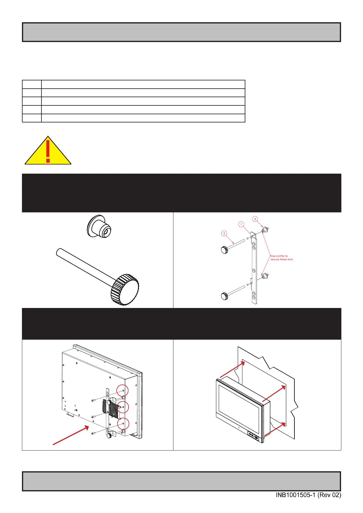
▼ 1: Locate 4 pcs of Thumb screw and Mounting
Socket Nut in separate form as illustrated below.
▼ 2: Locate both left and right brackets, and assemble the
Thumb Screws with Mounting Socket nut as illustrated.
1: Console Bracket. 2: RAMPA-CAP NUTS.
3: Thumb (wingnut) Screw DIN 912 M5x70
NOTE: Apply Loctite to Thumb Screw/Socket Nut.
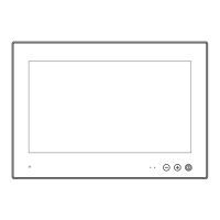
▼ 3: Mount the right bracket on the right rear side of
unit rst with 3 x M5x12 Countersunk Hex screws as
illustrated and fasten it using Torque Force 3.75nm
▼ 4: Tilt the unit 45 degree to allow the right bracket to
enter cutout rst, then tilt it back 45 degree and slide the
entire unit into the cutout evenly and carefully. User Controls
and Connector Area should be facing downwards.