90
IND100241-37
Appendix
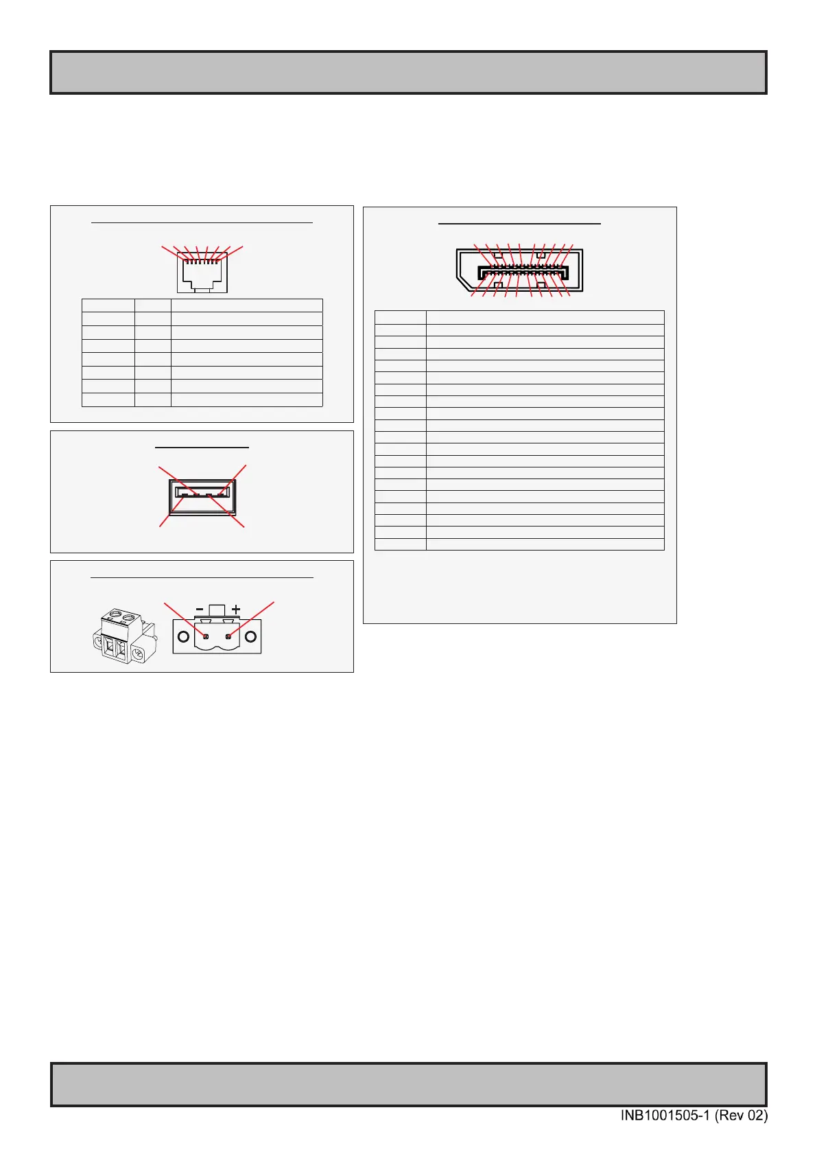
Pinout Assignments
8-pin RJ45 10/100/1000Mbps LAN/Ethernet
1 2 3 4 5 6 7 8
PIN 01 D0P+ Differential Pair 0 (Positive)
PIN 02 D0N- Differential Pair 0 (Negative)
PIN 03 D1P+ Differential Pair 1 (Positive)
PIN 04 D2P+ Differential Pair 2 (Positive)
PIN 05 D2N- Differential Pair 2 (Negative)
PIN 06 D1N- Differential Pair 1 (Negative)
PIN 07 D3P+ Differential Pair 3 (Positive)
PIN 08 D3N- Differential Pair 3 (Negative)
Connectors illustrated here are either standard by factory default or may be available (through factory customization).
Note that some combinations may not be possible due to space restrictions. List also valid for customized models. All
pin out assignments are seen from users Point of View (POV) while looking straight at the connector. Please review
the dedicated datasheet or technical drawings for your actual unit to identify and determine the presence of desired
connector. Detailed information about Housing Connectors (terminal blocks) can be found earlier in this manual.
4-pin USB TYPE A
Pin 2: Negative Data
Pin 1: VCC +5V
Pin 3: Positive Data
Pin 4: Ground
2-pin Terminal Block 5.08 - DC Power Input
Pin 2: Negative - Pin 1: Positive +
20-pin DisplayPort (DP) Female
20 18 16 14 12 10 8 6 4 2
19 17 15 13 11 9 7 5 3 1
PIN 01 ML_Lane 0 (p) - Lane 0 (positive)
PIN 02 GND - Ground
PIN 03 ML_Lane 0 (n) - Lane 0 (negative)
PIN 04 ML_Lane 1 (p) - Lane 1 (positive)
PIN 05 GND - Ground
PIN 06 ML_Lane 1 (n) - Lane 1 (negative)
PIN 07 ML_Lane 2 (p) - Lane 2 (positive)
PIN 08 GND - Ground
PIN 09 ML_Lane 2 (n) - Lane 2 (negative)
PIN 10 ML_Lane 3 (p) - Lane 3 (positive)
PIN 11 GND - Ground
PIN 12 ML_Lane 3 (n) - Lane 3 (negative)
PIN 13* CONFIG1 - connected to Ground*
PIN 14* CONFIG2 - connected to Ground*
PIN 15 AUX CH (p) - Auxiliary Channel (positive)
PIN 16 GND - Ground
PIN 17 AUX CH (n) - Auxiliary Channel (negative)
PIN 18 Hot Plug - Hot Plug Detect
PIN 19 Return - Return for Power
PIN 20 DP_PWR - Power for connector (3.3 V 500 mA)
*Pins 13 and 14 may either be directly connected to ground or
connected to ground through a pulldown device. This is the pinout for
source-side connector, the sink-side connector pinout will have lanes
0–3 reversed in order; i.e., lane 3 will be on pin 1(n) and 3(p) while
lane 0 will be on pin 10(n) and 12(p).