32
Installation Procedures
Installation
IND100078-73
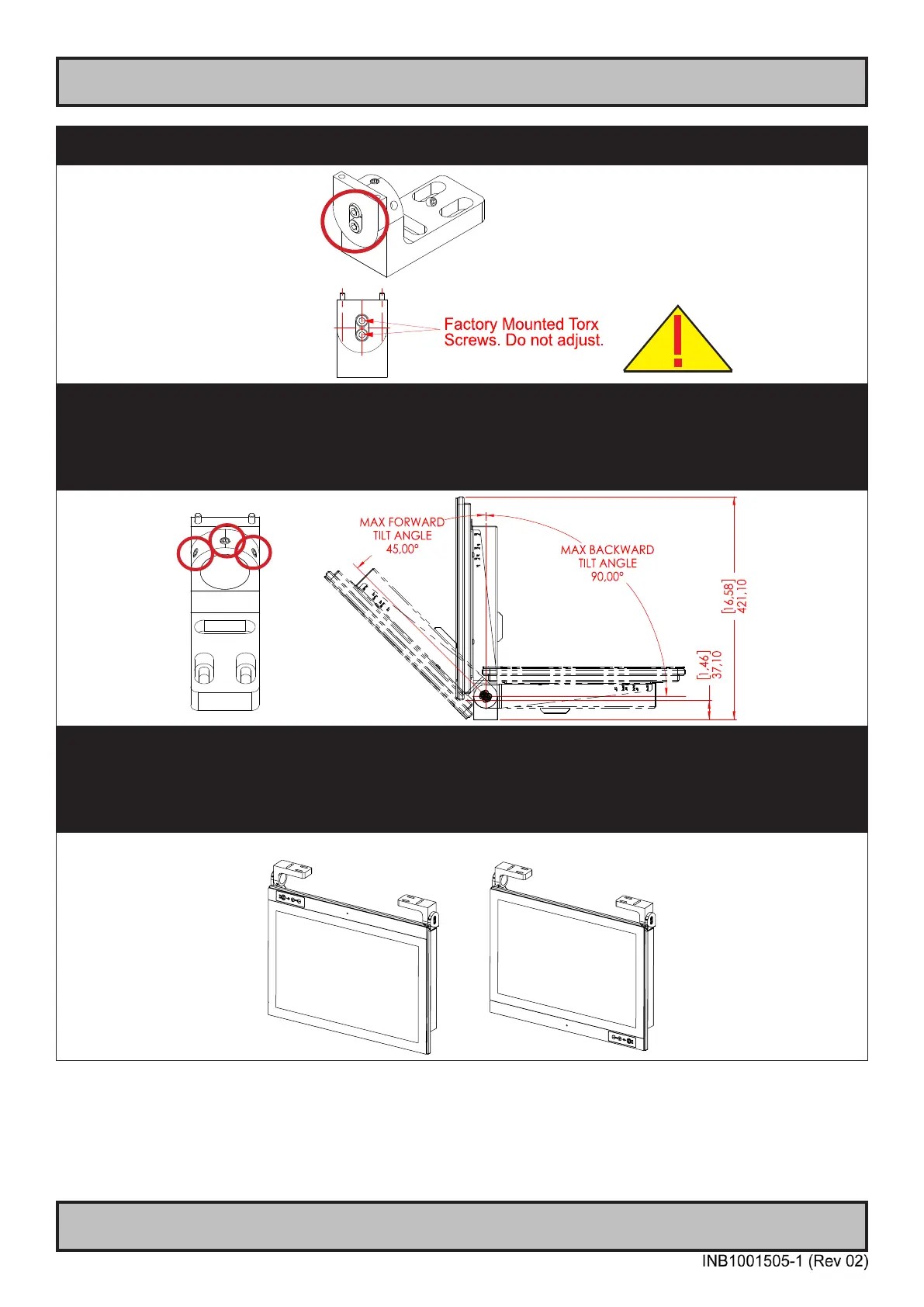
▼ 5: Please note the Factory Mounted Torx screws on both bracket sides, THESE ARE NOT TO BE ADJUSTED OR
LOOSENED!
▼ 6: Fasten the complete unit to your table/desktop location, and tilt it into the desired position. Locate the Set Socket Screws
on both brackets decribed in step 3. Tighten minimum 2 of 3 for each arm to secure position, use Torque Force 7Nm on all. If
you need to re-adjust the tilting later, place your hand on top of the unit to keep it steady, and loosen minimum two of any Set
Top Screws on both brackets, adjust unit into new tilting angle, and fasten the Set Top Screws again. Veriy that the unit does
not tilt by itself and appear xed in-place. Note: Tilt Angle below is illustrated for 23.8 inch. 21.5 and 27.0 inch are approximately
the same
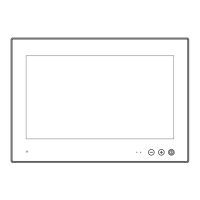
▼ Alternative Mounting: Depending on installation needs, you may mount the complete unit in ceiling in two different ways.
Upside Down Position: User Controls will be upside down, cables go straight up. Displayed image needs to be ipped
vertically (via Graphics Driver/Options/Operating System).
Normal Position: User Controls readable, no image ip needed, cables has to bend up or go straight down.
Upside Down
Normal Position