Specications - NMEA / IEC COM Module RS-422 / RS-485
PCA100293-1
55
IND100129-138
SPECIFICATIONS
Note: All specifi cations are subject to change without prior notice!
Please visit www.hattelandtechnology.com for the latest electronic version.
NMEA Standards:
IEC61162-1 chapter 3.5.5 state that the input shall withstand 15V between ground and input. The reference speed
specified is set at 4800 bit/s.
IEC61162-2 chapter 3.1 state that there are 3 wires to be used. (A, B and C). The reference speed for this interface is
set as 38400 bit/s.
Please visit http://www.iec.ch (International Electrotechnical Commission) for the complete standard description.
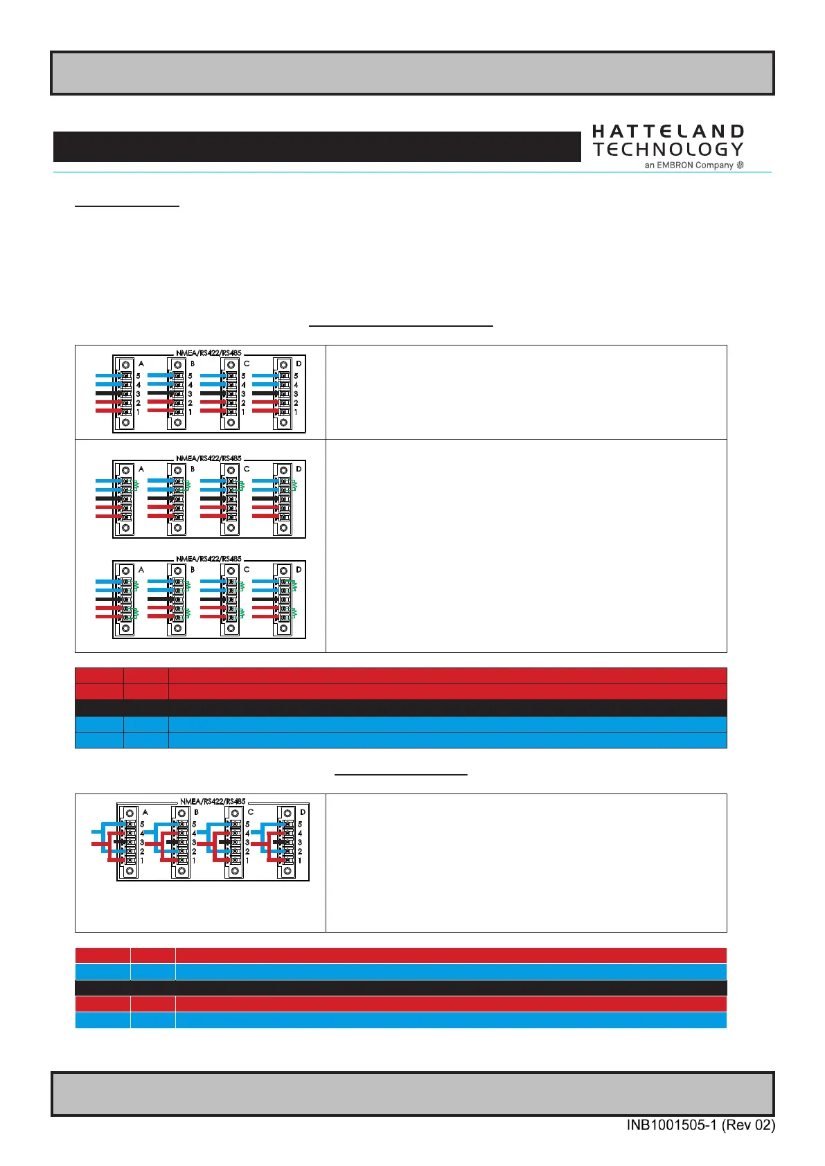
RS-422 / RS-485 FULL DUPLEX
Without Termination:
- Black is always connected
- Blue is connected when the device acts as a receiver
- Red is connected when the device acts as a transmitter
Total 5 wires.
If unit is master
R
R
R
R
If unit is slave
R
R
R
R
R
R
R
R
With Termination:
- Black is always connected
- Blue is connected when the device acts as a receiver
- Red is connected when the device acts as a transmitter
Total 5 wires +
Termination (if unit is master):
1 x 110/120 Ω resistor between PIN 4 (RxD-) and 5 (RxD+).
Termination (if unit is slave):
2 x 110/120 Ω resistor between PIN 4 (RxD-) and 5 (RxD+) and
PIN 1 (TxD-) and PIN 2 (TxD+).
For each pair there shall be one termination resistor (110/120Ω) at
each end of the bus. (A total of 2 resistors on each pair).
PIN 01 TxD- Transmit Data Negative
PIN 02 TxD+ Transmit Data Positive
PIN 03 GND Isolated Ground
PIN 04 RxD- Receive Data Negative
PIN 05 RxD+ Receive Data Positive
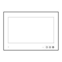
RS-485 HALF DUPLEX
- Black Pin 3 is always connected
- Blue is DATA+ (TxD+ connected to RxD+. Pin 5 and 2)
- Red is DATA - (TxD- connected to RxD-. Pin 4 and 1)
Total 3 wires.
Notes:
- Force TX OFF and (Normally) NO ECHO must be set.
- For each pair there shall be one termination resistor (110/120Ω) at
each end of the bus. (A total of 2 resistors on each pair).
PIN 01 TxD- Transmit Data Negative
PIN 02 TxD+ Transmit Data Positive
PIN 03 GND Isolated Ground
PIN 04 RxD- Receive Data Negative
PIN 05 RxD+ Receive Data Positive