Specications - Isolated Digital Input/Output Module
PCA100297-1
57
IND100129-169
All specifications are subject to change without prior notice!
SPECIFICATIONS
Note: All specifi cations are subject to change without prior notice!
Please visit www.hattelandtechnology.com for the latest electronic version.
Supported Operating Systems (OS)
Embedded Enterprise (WEE):
- Microsoft® Windows® Server 2003/2008/2008R2 (Eng)
- Microsoft® Windows® 2003/2008/2008R2 (Eng)
- Microsoft® Windows® 7 Professional/Ultimate (Eng, SP1)
- Windows® 10 IoT Enterprise 2016 LTSB
Linux:
Kernel 3.0.0-19 or above
Note: Listed Operating Systems above are hardware/platform dependent. Please check datasheet for specic unit if OS is supported.
Currently supported D2XX Drivers
Processor Architecture
Operating System (OS) Release Date (yyyy-mm-dd) x86 (32-bit) x64 (64-bit) Comments [Footnote]
Microsoft® Windows®* 2013-02-20 2.08.28 2.08.28
2.08.28 WHQL Certified [*1]
Release Notes [*2]
Linux 2012-06-29 1.1.12 1.1.12 [*3]
*includes the following versions of the Microsoft® Windows® operating systems:
Windows® XP, Windows® Server 2003, Windows® Vista, Windows® Server 2008, Windows® 7, Windows® Server 2008 R2 and Windows® 8.
For updates, please visit: http://www.ftdichip.com/Drivers/D2XX.htm
Footnotes:
[*1] = http://www.ftdichip.com/Drivers/CDM/CDM20828_Setup.exe
[*2] = http://www.ftdichip.com/Drivers/CDM/CDM%202%2008%2030%20Release%20Info%20for%208.1.rtf
[*3] = http://www.ftdichip.com/Drivers/D2XX/Linux/ReadMe-linux.txt
Getting started, documentation and specific Hatteland Technology Library links:
http://www.ftdichip.com/Support/Documents/ProgramGuides/D2XX_Programmer%27s_Guide(FT_000071).pdf
https://www.hattelandtechnology.com/hubfs/pdf/misc/doc101781-1_programmer_guide_ht00273opt-a1.pdf
https://www.hattelandtechnology.com/hubfs/drivers/dio_pca100297-1_ht00273opt-a1_package.zip
Additional
• Cable connector (MC 1,5/ 5-STF-3,81) Terminal Block 3.81 (see illustration below)
• Recommended Cable Thickness Minimum 22 AWG - Maximum 18 AWG
• Test and certicate Hatteland Technology standard, (tested / type approved by the following classification societies):
IEC 60945 4th (EN 60945:2002), IACS E10, EU RO MR - Mutual Recognition,
ClassNK - Nippon Kaiji Kyokai
• Safety IEC60950 The DIO module is intended to be used in control circuits and does therefore need external fuse to meet
safety agency approvals.
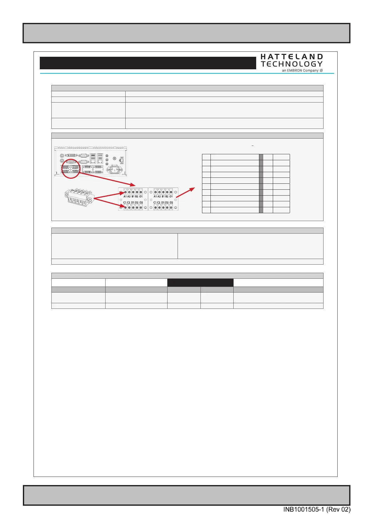
Illustration and Pinning
Note: Product below for illustration only. Location of module and product size/design may differ. Connector/pinning/specifications remain the same.
5-pin Terminal Block 3.81
Module A Module B
Pinout Assignments
70
IND100241-13
Appendix
25-pin Female Parallel (Optional for selected computers)
3 C
13 12 11 10 9 8 7 6 5 4 3 2 1
25 24 23 22 21 20 19 18 17 16 15 14
Pin 01 STROBE This signal indicates to the printer that data at PD7..0 are valid.
Pin 02 DATA0 Parallel data bus from PC board to printer. The data line are able to operate in PS/2 compatible bi-directional mode.
Pin 03 DATA1 Same as Pin 02
Pin 04 DATA2 Same as Pin 02
Pin 05 DATA3 Same as Pin 02
Pin 06 DATA4 Same as Pin 02
Pin 07 DATA5 Same as Pin 02
Pin 08 DATA6 Same as Pin 02
Pin 09 DATA7 Same as Pin 02
Pin 10 ACK Signal from printer indicating that the printer has received the data and is ready to accept further data.
Pin 11 BUSY Signal from printer indicating that the printer cannot accept further data.
Pin 12 PE Signal from printer indicating that the printer is out of paper.
Pin 13 SELECT Signal from printer to indicate that the printer is selected.
Pin 14 AUTO FEED This active low output causes the printer to add a line feed after each line printed.
Pin 15 ERR# Signal from printer indicating that an error has been detected.
Pin 16 INIT# This active low output initialises (resets) the printer.
Pin 17 SLIN# Signal to select the printer sent from CPU board to printer.
Pin 18 GND Ground
Pin 19 GND Ground
Pin 20 GND Ground
Pin 21 GND Ground
Pin 22 GND Ground
Pin 23 GND Ground
Pin 24 GND Ground
Pin 25 GND Ground
10+10 pin Isolated Digital Input/Output Module
Type Number “HT00268 OPT-A1”
3 C
Module A Module B
Module A Module B
A1 External Power + A1 IN+[0]
A2 N/C (Not Connected) A2 IN-[0]
B1 External Power - (GND1) B1 IN+[1]
B2 N/C (Not Connected) B2 IN-[1]
O1 HS[0] O1 N/C
C1 HS[1] C1 IN+[2]
C2 N/C (Not Connected) C2 IN-[2]
D1 HS[2] D1 IN+[3]
D2 N/C (Not Connected) D2 IN-[3]
O2 HS[3] O2 N/C
10-pin DisplayPort (DP) Female
D
20 18 16 14 12 10 8 6 4 2
19 17 15 13 11 9 7 5 3 1
PIN 01 ML_Lane 0 (p) - Lane 0 (positive)
PIN 02 GND - Ground
PIN 03 ML_Lane 0 (n) - Lane 0 (negative)
PIN 04 ML_Lane 1 (p) - Lane 1 (positive)
PIN 05 GND - Ground
PIN 06 ML_Lane 1 (n) - Lane 1 (negative)
PIN 07 ML_Lane 2 (p) - Lane 2 (positive)
PIN 08 GND - Ground
PIN 09 ML_Lane 2 (n) - Lane 2 (negative)
PIN 10 ML_Lane 3 (p) - Lane 3 (positive)
PIN 11 GND - Ground
PIN 12 ML_Lane 3 (n) - Lane 3 (negative)
PIN 13* CONFIG1 - connected to Ground*
PIN 14* CONFIG2 - connected to Ground*
PIN 15 AUX CH (p) - Auxiliary Channel (positive)
PIN 16 GND - Ground
PIN 17 AUX CH (n) - Auxiliary Channel (negative)
PIN 18 Hot Plug - Hot Plug Detect
PIN 19 Return - Return for Power
PIN 20 DP_PWR - Power for connector (3.3 V 500 mA)
*Pins 13 and 14 may either be directly connected to ground or
connected to ground through a pulldown device. This is the pinout for
source-side connector, the sink-side connector pinout will have lanes
0–3 reversed in order; i.e., lane 3 will be on pin 1(n) and 3(p) while
lane 0 will be on pin 10(n) and 12(p).