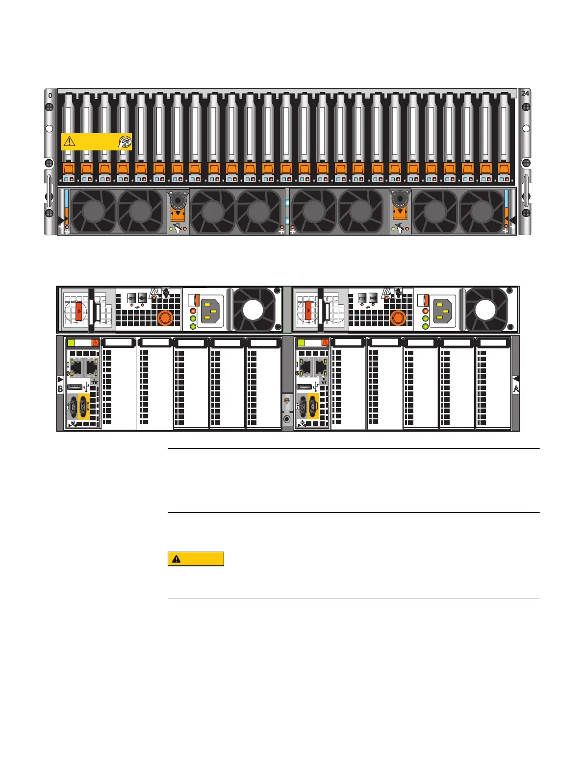
Figure 4 Front and rear view of DPE
Front
Disk-processor enclosure (Jetfire)
A
B
SP
SP
Will Make the Array Unusable
Caution: Array Software on drives 0-3. Removing or relocating them
01
01
AC
DC
!
1
0
1
0
X4
AC
DC
!
X4
X4
X4
AB
The DPE contains two storage processors (SP A and SP B). Each SP contains a
management module and five slots for I/O modules, numbered 0-4. SP slots that do not
support I/O modules are labeled.
Installing the disk processor enclosure
DO NOT lift the DPE by its I/O module handles. Use two people to lift the DPE on each
side.
Refer to Figure 6 on page 23 while performing the procedure that follows.
Procedure
1. Locate the Product ID/SN from the product serial number tag (PSNT) located on the
back of the DPE as shown in Figure 5 on page 22.
Assemble components in your cabinet
Installing the disk processor enclosure 21

 Loading...
