cables. Each BE loop can support up to 10 DAEs. For more details on additional DAE
cabling, see your VNX hardware information guide.
Power up additional DAEs
The DAE power cables are conveniently color-coded. Two colors identify the different
zones (PDUs):
l
Gray power cables connect to PDU A
l
Black power cables connect to PDU B
The DAE power cables should be connected directly to the PDUs.
Connect 2U, 25-drive DAE power cables
Before you begin
Ensure that the cabinet circuit breakers are still on and the PDUs are powered on.
Refer to Figure 20 on page 43 while performing the procedure to power up each 2U DAE
included in your system.
Procedure
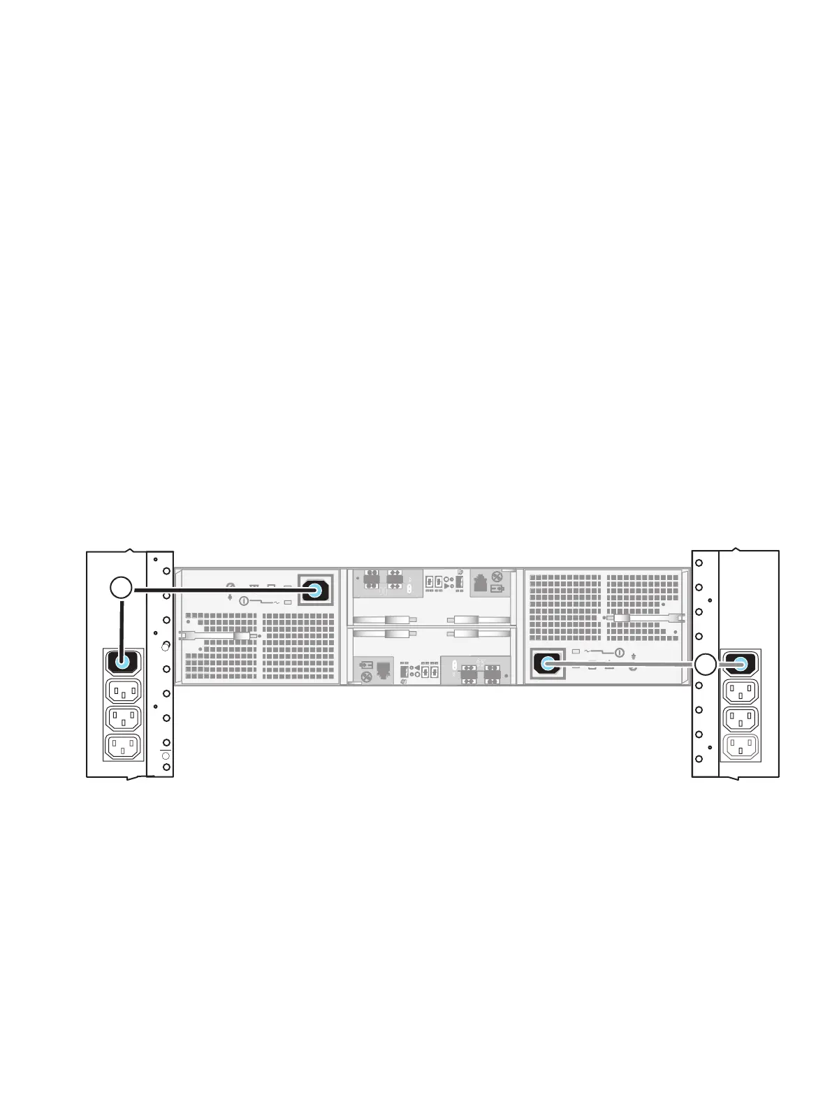
1. Connect or verify that the A-side DAE power cable is connected to PDU A. See cable 1.
2. Connect or verify that the B-side DAE power cable is connected to PDU B. See cable 2.
Figure 20 Power up a 2U DAE
Connect 3U, 15-drive DAE power cables
Before you begin
Ensure that the cabinet circuit breakers are still on and the PDUs are powered on.
Refer to Figure 21 on page 44 while performing the procedure to power up each 3U DAE
included in your system.
Procedure
1. Connect or verify that the A-side DAE power cable is connected to PDU A. See cable 1.
2. Connect or verify that the B-side DAE power cable is connected to PDU B. See cable 2.
Add additional storage
Power up additional DAEs 43

 Loading...
