Cabling to the 4U 60 drive DAE and the 3U 120 drive DAE are not shown because they
are not customer-installable.
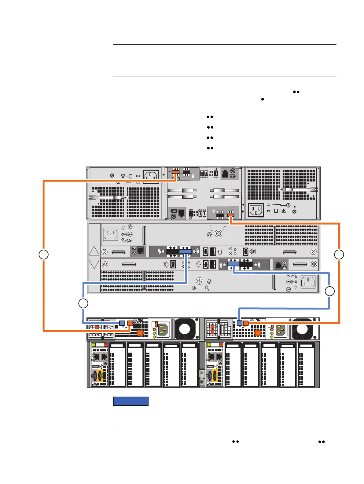
For steps 2 on page 42 through 5 on page 42, connect the following cables from
the SAS ports of the DPE to the LCC ports marked with double circles ( ) on the DAEs.
The cable ends to the LCC are marked with single circles ( ) on the cable connectors
as shown in Figure 17 on page 41. Ensure that the cables lock into place.
2. Connect SP A SAS 1 to DAE 1 LCC A ( ). See cable 1.
3. Connect SP B SAS 1 to DAE 1 LCC B ( ). See cable 2.
4. Connect SP A SAS 0 to DAE 2 LCC A ( ). See cable 3.
5. Connect SP B SAS 0 to DAE 2 LCC B ( ). See cable 4.
Figure 19 Cabling the first two DAEs to the storage processors
A
B
#
X4
6Gb SAS
#
X4
6Gb SAS
6 Gb
SAS
X4
#
6 Gb
SAS
X4
#
B
A
AC
DC
!
1
0
1
0
X4
AC
DC
!
X4
X4
X4
B
A
2
4
1
3
Identify the cables by the cable labels and the connectors. The cables and ports are
not colored. Bus 0 is identified with orange labels. Bus 1 uses blue labels.
Additional DAEs, up to the system maximum, can be added by extending the loop,
connecting cables from LCC A and B of a DAE ( ) to the appropriate LCC ports ( ) of
an additional DAE. Cables from DAE to DAE on these loops are mini-SAS to mini-SAS
Add additional storage
42 EMC VNX Series VNX5400 Block Installation Guide

 Loading...
