October 2015
Service Instructions
127072E Rev. C
17
Section 3: Actuator Reassembly
Actuator Reassembly
3�3�11 Coat one piston seal (4-60) with uid and install into the piston external seal groove.
CAUTION: INSTALL PISTON SEAL CORRECTLY
Install the piston seal with energizer ring facing the outside edge of piston (3-30).
3�3�12 Refer to assembly drawing page 2 of 2 Detail "C". Coat Polypak seal (4-30) with
hydraulic uid and install, lip rst, into inner end cap (3-10).
CAUTION: INSTALL POLYPAK SEAL CORRECTLY
Install the Polypak seal with energizer ring facing piston side of inner end cap (3-10).
3�3�13 Install rod bushing (4-20) into inner end cap (3-10).
3�3�14 Install rod wiper (4-10) into inner end cap (3-10).
3�3�15 Install one O-ring seal (4-90) into inboard face of inner end cap (3-10).
3�3�16 Install inner end cap (3-10) onto piston rod (3-40).
3�3�17 Install two tie bars (3-20) into inner end cap (3-10).
NOTE:
The tie bars should be installed across from each other.
3�3�18 Install one O-ring seal (4-40) into inboard face of outer end cap (3-80).
3�3�19 Install outer end cap (3-80) into open end of cylinder (3-70).
NOTE:
The pressure inlet ports of the inner and outer end caps should be positioned in the same
position as recorded in Section 2 step 2.2.1.
3�3�20 Install the remaining tie bars (3-20) through outer end cap (3-80) and into inner
end cap (3-10). Screw all tie bars (3-20) into inner end cap until dimension "A" (as
shown on assembly drawing page 1 of 2) is achieved.
3�3�21 Install lockwashers (3-95) onto tie bars (3-20) and up against outer end cap (3-80).
3�3�22 Install hex nuts (3-90) onto tie bars (3-20) and up against lockwashers (3-95).
3�3�23 Torque tighten hex nuts (3-90) until a nal lubricated torque, as listed in the
following table, has been achieved.
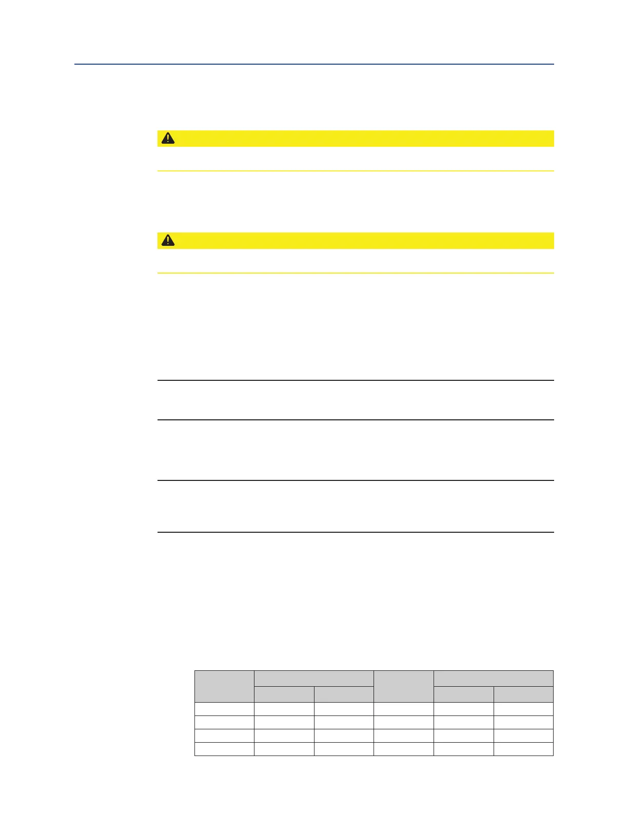
Table 3� Tie Bar Nuts (3-90) Torque Table
Model
TORQUE (±5%)
Model
TORQUE (±5%)
Lbf-ft� N-m Lbf-ft� N-m
G01 70 95 G5 385 522
G2 70 95 G7 580 786
G3 70 95 G8 580 786
G4 135 183 G10 1000 1356
 Loading...


