October 2015
Service Instructions
127072E Rev. C
23
Section 5: Module Removal and Installation
Module Removal and Installation
NOTE:
To identify hex cap screws (7-100) from hex cap screws (7-80), hex cap screws (7-100) will
be located to the left and right of spring-return cartridge top dead center and will then be
counted as every other hex cap screw. To verify correct hex cap screws check the following
table for screw length.
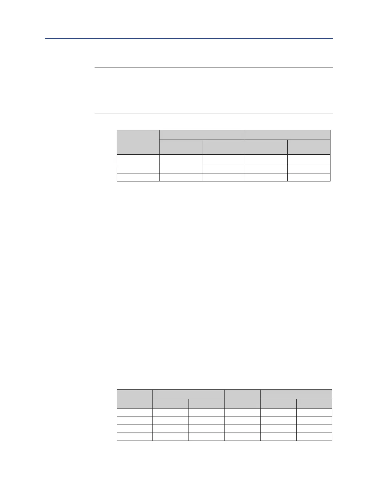
Table 4� Wire Length Requirements
MODEL
G/GC/GH/
GHC
ITEM 7-80 LENGTH ITEM 7-100 LENGTH
Inches mm Inches mm
G7 2 50.8 2.75 69.85
G8 3 76.2 4.5 114.3
G10 3.5 88.9 5.0 127
5�1�6�2 Remove override cylinder assembly from spring cartridge assembly (5-10).
5�2 M11 Override Cylinder Installation
5�2�1 Install O-ring seal (6-10) into the O-ring groove in the outboard end of spring
cartridge assembly (5-10).
5�2�2 M11 hydraulic override cylinder installation: For models G01 through G5 use step
5.2.3 and for G7 through G10 use step 5.2.4.
5�2�3 G01 through G5 M11 override cylinder installation
5�2�3�1 Insert M11 hydraulic override cylinder assembly through spring cartridge
outer end.
5�2�3�2 Install lockwashers (7-90) on to hex cap screws (7-80).
5�2�3�3 Install hex cap screws (7-80) with lockwashers (7-90) through hydraulic
override end cap (7-70) and into outer end of spring cartridge (5-10).
5�2�4 G7 through G10 M11 override cylinder installation
5�2�4�1 Insert M11 hydraulic override cylinder assembly into spring cartridge
outer end.
5�2�4�2 Install lockwashers (7-90) on to eight hex cap screws (7-100).
5�2�4�3 Install hex cap screws (7-100) with lockwashers (7-90) through hydraulic
override end cap (7-70) and into outer end of spring cartridge (5-10).
5�2�5 Torque tighten hex cap screws (7-100 and 7-80), alternately until a nal lubricated
torque, as listed in the following table, has been achieved.
Table 5� M11 Override Cylinder End Cap to SR Cartridge Screw Torque
Model
TORQUE (±5%)
Model
TORQUE (±5%)
Lbf-ft� N-m Lbf-ft� N-m
G01 16 21.68 G5 40 54.2
G2 16 21.68 G7 80 108.4
G3 16 21.68 G8 130 176.15
G4 40 54.2 G10 190 257.45
 Loading...


