October 2015
Service Instructions
127072E Rev. C
27
Section 5: Module Removal and Installation
Module Removal and Installation
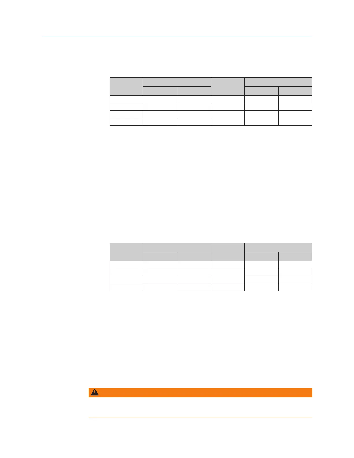
5�4�6 Torque tighten the spring cartridge tension rod as listed in the following table.
Table 7� Spring Cartridge Tension Rod Torque Table
Housing
Model
TORQUE (±5%)
Housing
Model
TORQUE (±5%)
Lbf-ft� N-m Lbf-ft� N-m
G01 50 68 G5 240 325
G2 90 122 G7 240 325
G3 90 122 G8 240 325
G4 240 325 G10 240 325
5�4�7 Install lock washers (5-30) onto hex cap screws (5-20).
5�4�8 Install hex cap screws (5-20) with lockwashers (5-30) through housing (1-10) and
into spring cartridge assembly (5-10) and tighten.
5�4�9 Install O-ring seal (6-10) into the O-ring groove in the outboard end of spring
cartridge assembly (5-10).
5�4�10 Install lockwashers (7-30) onto hex cap screws (7-20).
5�4�11 Install end cap (7-70) onto the outboard end of spring cartridge assembly (5-10).
5�4�12 Install and tighten hex cap screws (7-80) with lockwashers (7-90) through end cap
(7-70) and into spring cartridge assembly (5-10).
5�4�13 Torque tighten hex cap screws (7-100 and 7-80) alternately until a nal lubricated
torque, as listed in the following table, has been achieved.
Table 8� Spring Cartridge Tension Rod Torque Table
Housing
Model
TORQUE (±5%)
Housing
Model
TORQUE (±5%)
Lbf-ft� N-m Lbf-ft� N-m
G01 16 21.68 G5 40 54.2
G2 16 21.68 G7 80 108.4
G3 16 21.68 G8 130 176.15
G4 40 54.2 G10 190 257.45
5�4�14 If removed install stop screw nuts (1-190) onto stop screws (1-180).
5�4�15 If removed install O-ring (2-90) onto stop screws (1-180).
5�4�16 If removed install two stop screws (1-180) into two stop screw holes on the front
of housing (1-10).
5�4�17 Adjust both stop screws (1-180) back to settings recorded earlier in Section 5.
5�4�18 Tighten both stop screw nuts (1-190) securely.
5�5 Hydraulic Power Module Removal
WARNING: CONFIRM EXTENDED SPRING POSITION
The spring cartridge must be checked to verify that the spring(s) are in their extended
position before the power module is removed from the actuator.
 Loading...


