S1400T-2808B Page 3-6 Section 3 - Grounding & Isolation
i This ground wire should be clamped or brazed to the Ground Bed Conductor (that is
typically a stranded copper AWG 0000 cable installed vertically or horizontally).
i The other end of the wire should be tinned with solder and either equipped with a
terminal connector (for case mounting) or inserted into a case mounted Ground Lug (if
supplied) (see Figure 3-6).
i The ground wire should be run such that any routing bend in the cable has a
minimum radius of 12-inches below ground and 8-inches above ground.
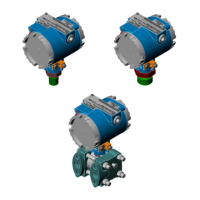
Figure 3-6 - Series 2808-XXB Transmitter Chassis Ground Wiring
Figure 3-6 shows a Series 2808-XXB Transmitter installation. An AWG 4 solid copper
ground wire should be connected to the 2808’s Case on the outside of the Transmitter’s
Electrical Housing and to Earth Ground. The units Earth Ground Cable should be clamped
to an exposed Ground Rod or to an AWG 0000 stranded copper Ground Cable that in turn
should be connected to either an Earth Ground Rod or Earth Ground Bed. Both ends of the
units Earth Ground Cable must be free of any coating such as paint or insulated covering
as well as any oxidation. The connecting point of the Ground Rod or AWG 0000 Ground
Cable must also be free of any coating and free of oxidation. Once the ground connection
has been established (at either the Ground Rod or Ground Cable) it should be covered or
coated to protect it from the environment.
Note that the recommended grounding convention for a Series 2808-XXB Transmitter is to
install the specified external AWG 4 (Max.) Earth Ground Cable between the Transmitter’s
Case (see Figure 3-6) and a known good Earth Ground.
3.3.3 Other Grounding Considerations
Gas lines require special grounding considerations. If a gas meter run includes a
thermocouple or RTD sensor installed in a thermowell, the well (not the sensor) must be
connected to a gas discharge-type lightning arrestor as shown in Figure 3-7. A copper braid,
brazed to the thermal well, is dressed into a smooth curve and connected to the arrestor as
shown. The curve is necessary to minimize arcing caused by lightning strikes or high static
surges. The path from the lightning arrestor to the ground bed should also be smooth and
free from sharp bends for the same reason.
 Loading...


