1B-8 / DP Transmitters 2808B
1B.4 TRANSMITTER MOUNTING
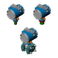
Transmitters may be mounted in any position. However, when a Transmitter leaves the
factory, it is calibrated for operation in the upright position with the electronics enclosure
at the top and the DP connections at the bottom as shown in Figure 1B-2. If it is installed in
a different position, the Transmitter may require a slight zero adjustment. This procedure
is described in Section 3 Calibration.
Transmitters are provided with connection ports on the process flange as the standard
arrangement. Optional manifold blocks may also be specified. Both arrangements are
described as follows:
Standard Process Flange. Two process flanges containing the connection ports are
assembled to the transmitter. The port designations (L and H) are stamped on the body of
the flanges. The ports accept 1/4-18 NPT pipe connections on 2-1/8 in. centers for
connection to the orifice taps or a standard three-valve manifold. The process flange
connections are illustrated at the top of Figure 1B-5.
Figure 1B-5 - Process Flange and Optional Manifold Block Connectors
The two process flange assemblies are held in place by four bolts and nuts. When the bolts
are removed, the flanges can be repositioned so that the connections can emanate from the
 Loading...


