Loop Powered Indicator Page 2 Appendix B
The two-board assembly is designed for field retrofit in the 2808 pressure transmitters.
1.1.3. Adjustments
Adjustment potentiometers are unnecessary in the LPI. The indicator is always scaled to 4-
20mA. The user configures the LPI in engineering units of their choice, i.e., mA, %, psi, IN
H2O, bar, kg/cm2, °C, °F or Custom.
1.1.4 Connectors
The LPI Assembly comes in two parts: The Meter Motherboard and the Meter/Display
Board. The Meter Motherboard is assembled into the Model 2808 Transmitter by
connecting the transmitter’s terminal block to the spade fingers integral to the Meter
Motherboard and installing the mounting screws through the Meter Motherboard to the
cast-in mounting bosses in the transmitter housing. The customer cable is then connected
to the compression-type terminals of Terminal Block TB1 on the Meter Motherboard.
Finally, the Meter/Display Board plugs into the Meter Motherboard in any one of four
positions depending on the desired meter rotation; this is through a set of two-conductor
“Berg” connectors. The Meter/Display Board is also secured to the Meter Motherboard with
four screws.
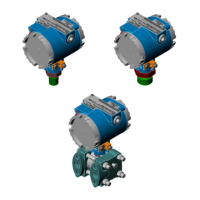
Figure 1-1 - 2808 with Loop Powered Indicator
 Loading...


