2808B DP Transmitters / 1B-9
front, rear or bottom of the Transmitter. Care should be taken not to damage the sensor
module assembly during this procedure. Once the flange has been positioned, the bolts
should be tightened in an alternating sequence to about 20-30 foot-pounds of torque.
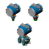
Optional Process Manifold Block. Process manifold blocks may be installed on the
Transmitter to permit the use of connector assemblies having different connection centers.
The manifold blocks, which are oval in appearance, mate with the Transmitter's process
flange. The blocks may be installed in several positions to achieve different connection
centers as shown in Figure 1B-5.
Vent Plug. Each process flange includes a 3/8 inch vent plug to bleed pressure lines. To
vent the unit, loosen the inner 5/32” Hex screw 1/4 turn. To perform calibration by applying
pressure to the flange, remove the plug with a 7/16” Hex Wrench and install a 1/4” NPT
fitting. Be sure to secure both plugs upon completion.
Warning! Both vents may be under high pressure! Never loosen them more than 1/4 turn to
bleed the lines. Secure both vents after bleeding is complete.
1B.4.1 Transmitter Housing Rotation
Once mounted, the Transmitter Housing can be rotated up to 180° in either direction, i.e.,
clockwise or counterclockwise. The Transmitter Housing must not be rotated from its
shipped position any more than 180° clockwise or counterclockwise. CAUTION: Trans-
mitter will be damaged if the Transmitter Housing is rotated more than 180° from
its shipped position.
To rotate the Transmitter Housing, the set screw that locks the Pressure Transducer to the
Transmitter Housing must be removed with a 3mm Hex Wrench. Once the Transmitter
Housing has been turned to the desired position, be sure to replace and tighten the set
screw (see Figure 1B-6).
 Loading...


