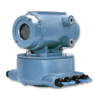
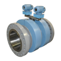
Figure 3-24: 3410 Series electronics
A. Terminal end of Transmitter Electronics Enclosure
B. Backplane board location
C. End cap security latch
D. Base enclosure with Acquisition Module
3.9.1
Replace the CPU Module or Optional I/O Module
Procedure
1. Remove power to the meter.
2. Disconnect security seals on the Transmitter Electronics Enclosure (see Figure
3-19), loosen the end cap security latches using a 3 mm Allen wrench (see Figure
3-20) and remove both end caps from the Transmitter Electronics Enclosure.
3. If replacing the CPU Module (terminal end of the enclosure) or the Optional I/O
Module, use a 6 mm flat blade screw driver and disconnect the CPU Module
terminal blocks (or the optional I/O Module terminal blocks).
Meter repairs Maintenance and Troubleshooting manual
June 2019 P/N 3-9000-769
88 Gas Ultrasonic Flow Meters

 Loading...


