5. Insert the new CPU Module or I/O Module into the enclosure and firmly push until
the board is fully seated into the Backplane Board connectors and the lock is
engaged.
6. Replace the terminal blocks for the CPU Module and/or the Optional I/O Module
and tighten the flat head screws with a 3 mm flat blade screw driver.
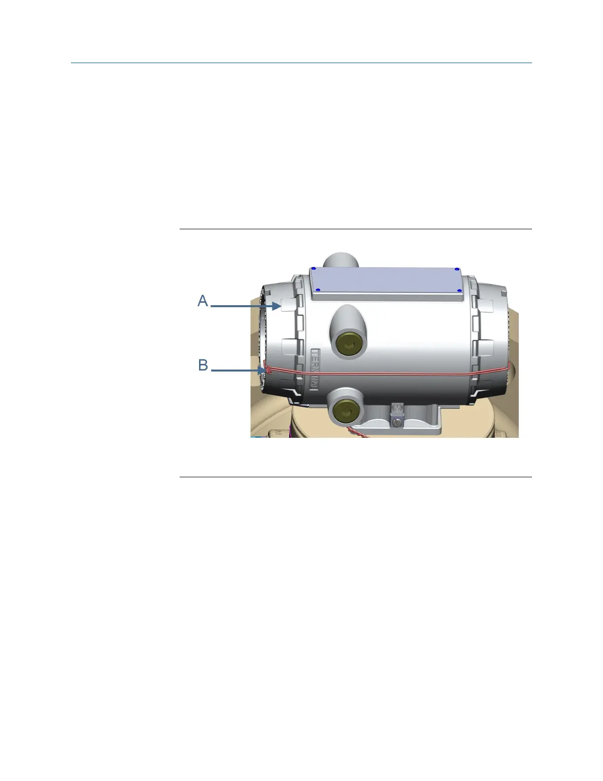
7. If you are not replacing other electronics, replace the end caps and security latches
(requires a 3 mm Allen wrench). If required, install the security seal wire into and
through one of the two holes in the end cap. Choose holes that minimize
counterclockwise rotation of the end cap when the security wire is taut (maximum
wire diameter .078 inch; 2.0 mm).
Figure 3-27: Transmitter electronic enclosure security seals
A. Transmitter Electronics Enclosure end cap
B. Security wire seals
8. Adjust the security wire, removing all slack and thread into the lead seal.
9. Cut wire ends to remove excess wire.
10. If replacing other electronics or the fuse, continue with Replace the Fuse, Replace
Backplane, I.S. Barrier or Power Supply board and Adquisition Module replacement
before replacing the end caps and sealing the enclosure.
11. If you encounter problems replacing the electronics, see the Lifecycle Customer
Service contact information on the back cover of this manual.
This completes the CPU Module or I/O Module replacement procedure.
3.9.2
Replace the Fuse
Procedure
1. Remove power to the meter.
Meter repairs Maintenance and Troubleshooting manual
June 2019 P/N 3-9000-769
90 Gas Ultrasonic Flow Meters

 Loading...


