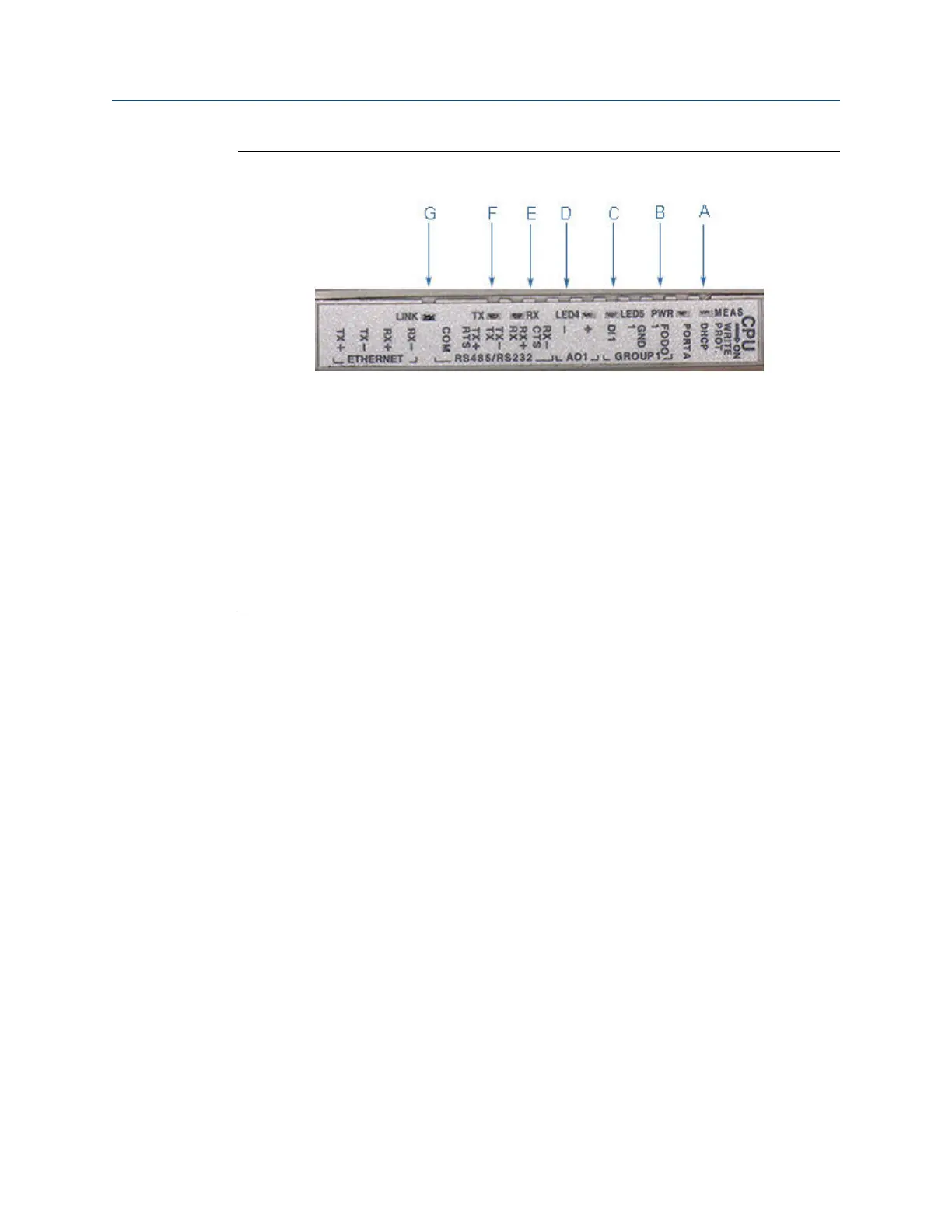
CPU Module labeling and LED indicators - Type 2Figure 3-7:
A. Acquisition/Measurement mode
B. Power
C. LED 5 - communication between CPU and Acquisition Module
D. LED 4 - link between CPU and Acquisition Module
E. RX (RS-485/RS-232) - receiving data
F. TX (RS-485/RS-232) - transmitting data (RS-485 2-wire use TX+ and TX-)
G. Link (Eth1 Link) - user Ethernet connection
Electrical installation
56 Gas Ultrasonic Flow Meter

 Loading...


