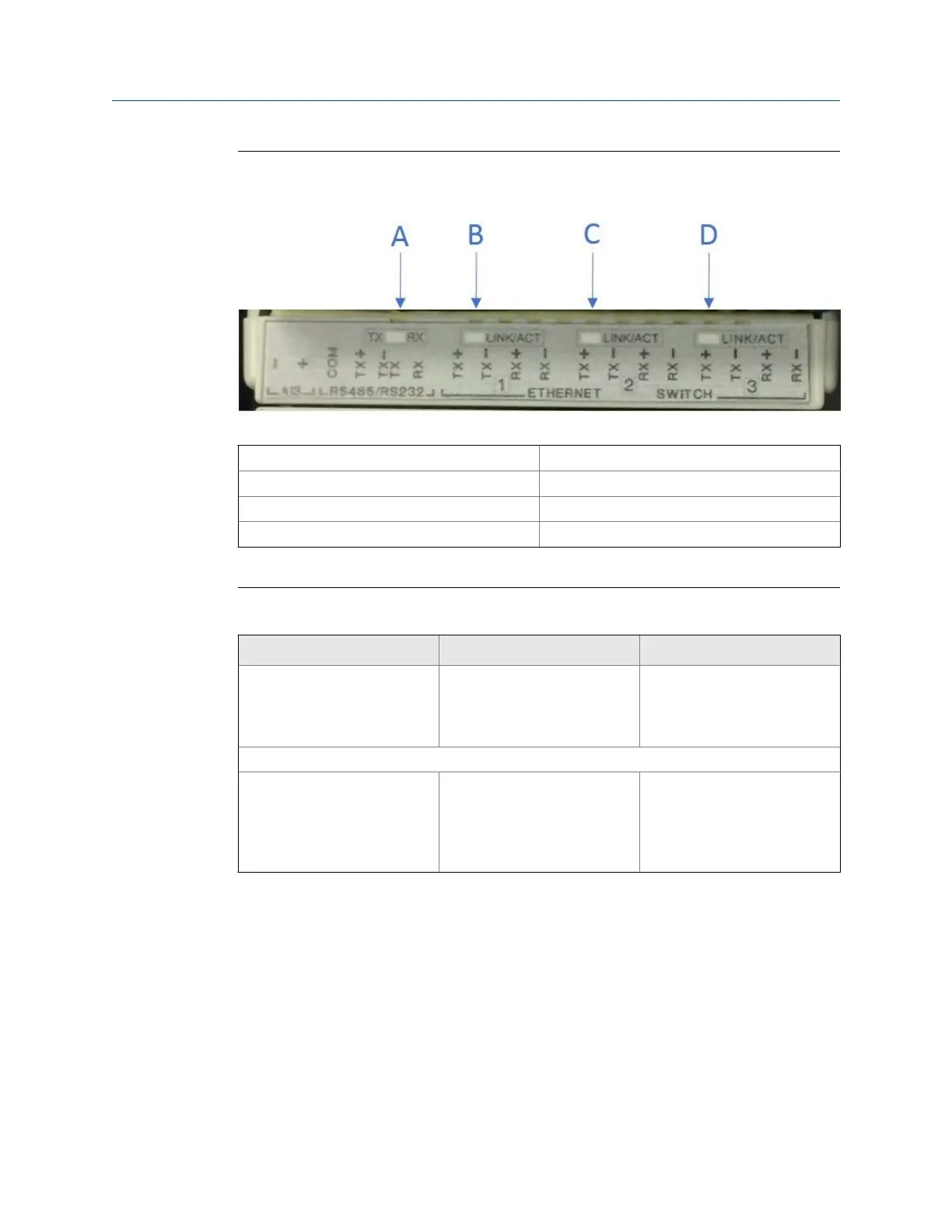
Expansion I/O LED indicatorsFigure 3-18:
A. TX/RX for RS232/RS485 serial port Flashing (Orange - RX/Green - TX)
B. Ethernet switch port 1 - Link/Activity indicator Flashing (Green)
C. Ethernet switch port 2 - Link/Activity indicator Flashing (Green)
D. Ethernet switch port 3 - Link/Activity indicator Flashing (Green)
Expansion I/O LED functions Table 3-7:
Expansion I/O Module LED Function LED
TX/RX RX/TX signal (Port B/C for
RS485 or RS232 communica-
tion) receiving and transmit-
ting data
• Flashing Orange - RX
• Flashing Green - TX
LINK/ACT
Ethernet Switch Port 1, 2, 3 • Link and Activity indicator
for each Ethernet switch
port.
• Separate indicator for each
Ethernet switch port
Flashing Green when Ethernet
activity present.
Frequency/Digital outputs
The meter has three user-configurable outputs that can be configured for either a
Frequency output or Digital output (FODO).
• FODO1 (eight possible parameter configurations) [Type 2] [Type 4]
• FODO2 (eight possible parameter configurations) [Type 2] [Type 4]
• FODO3 (eight possible parameter configurations) [Type 2] [Type 4]
• FODO4 (eight possible parameter configurations) [Type 4]
Electrical installation
72 Gas Ultrasonic Flow Meter

 Loading...


