4.3.6 LME communication connectivity restrictions
The pickoff input signal connections are made at terminal strip connection TB2 for
Channel A, and TB3 for Channel B. Power supply and output signal connections are made
at terminal strip TB1. Refer to Table 2-7, Table 2-8, Table 2-9 and Table 2-10.
Important
• For single channel wiring use multi-conductor control and instrumentation cable
(18AWG), or equivalent.
• Earth ground shield at one end only.
• Insulate the shield at the other end.
• For dual channel wiring use multi-conductor control and instrumentation cable
(18AWG), or equivalent.
• Connect both shields to earth ground at one end of the cables and insulate the shields
at the other end.
• The LME housing should be at earth ground.
4.3.7
RME communication connectivity restrictions
The RME must follow all the connectivity restrictions that are applicable to the LME as well
as the transmission distance restrictions listed on Table 4-4.
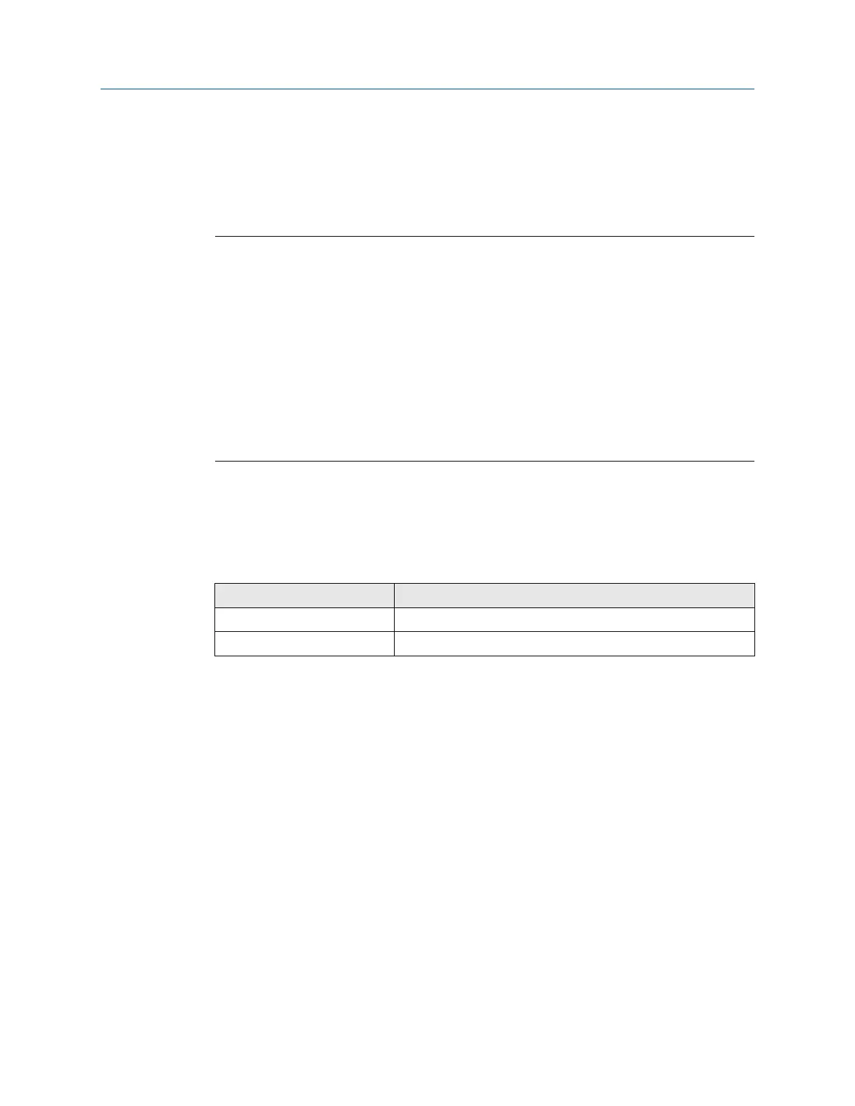
Table 4-4: Installation dimensions for the RME
Device Transmission distance
Pickoff to RME 6.1 meters (20 ft.) maximum from RME dual channel
Preamplifier to receiver 1525 meters (5,000 ft.) maximum
Prepare the turbine meter for use User manual
March 2019 P/N 3-9008-515
66 Daniel Series 1500 Liquid Turbine Meter, NPS 3-24
 Loading...