EN Series Drives Manual
External Connector Interface (ECI-44, Optional)
The ECI-44 allows access to all command and input and output signals. The
ECI-44 should be mounted close to the drive and away from any high voltage
wiring.
The ECI-44 comes complete with the hardware necessary for mounting to most
DIN rail mounting track (see mounting dimensions below).
r;EMERSON
morappr CONTROII
ECI
PIN980300
REV Al
9
SYNC ENCe001 INfIrrt norm -ax 1.493 1 °G 2
- 'AAR B27 ; • i
#4040.0000 0.0.44000•61000001,
Ilit0.00001.1014100001i
*4-4 0001
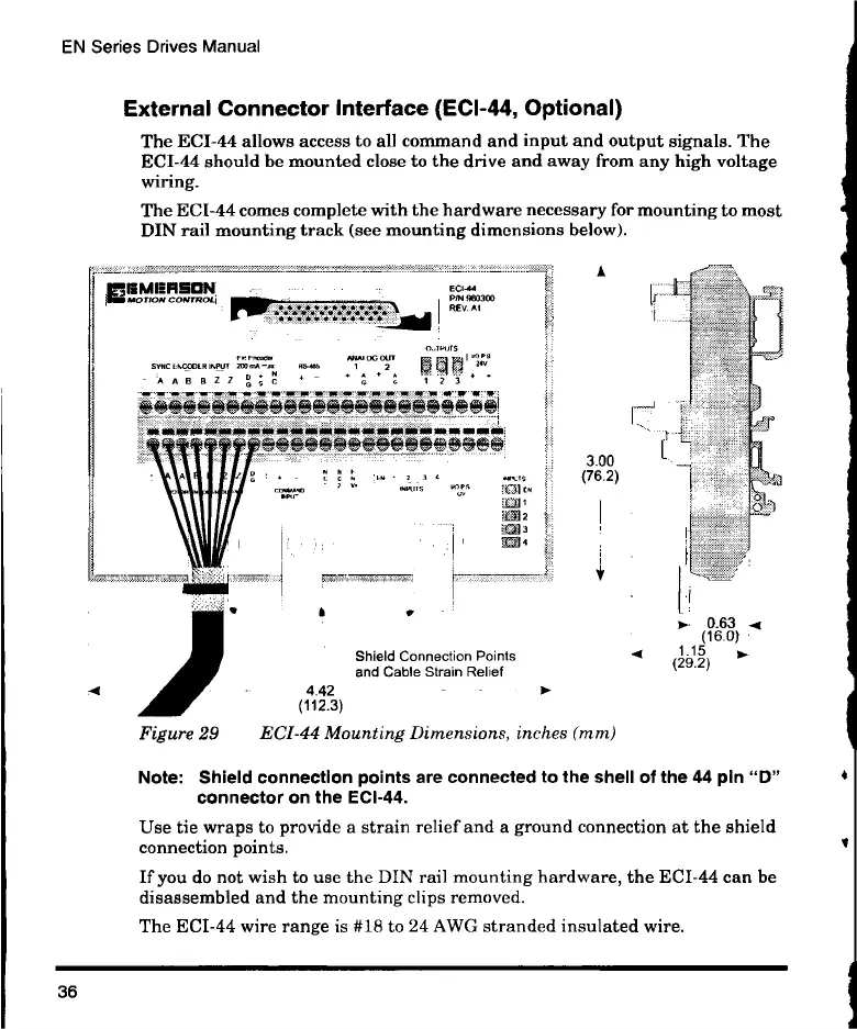
Figure 29
Shield Connection Points
and Cable Strain Relief
4.42
(112.3)
ECI-44 Mounting Dimensions, inches (mm)
A
3.00
(76.2)
1
ID- 0.63 -4
(16.0)
1.15 )1,-
(29.2)
Note: Shield connection points are connected to the shell of the 44 pin "D"
connector on the ECI-44.
Use tie wraps to provide a strain relief and a ground connection at the shield
connection points.
If you do not wish to use the DIN rail mounting hardware, the ECI-44 can be
disassembled and the mounting clips removed.
The ECI-44 wire range is #18 to 24 AWG stranded insulated wire.
36
 Loading...