Installation
Note: Wiring should be done with consideration for future troubleshooting
and repair. All wiring should be either color coded and/or tagged with
Industrial wire tabs. Low voltage wiring should be routed away from
high voltage wiring.
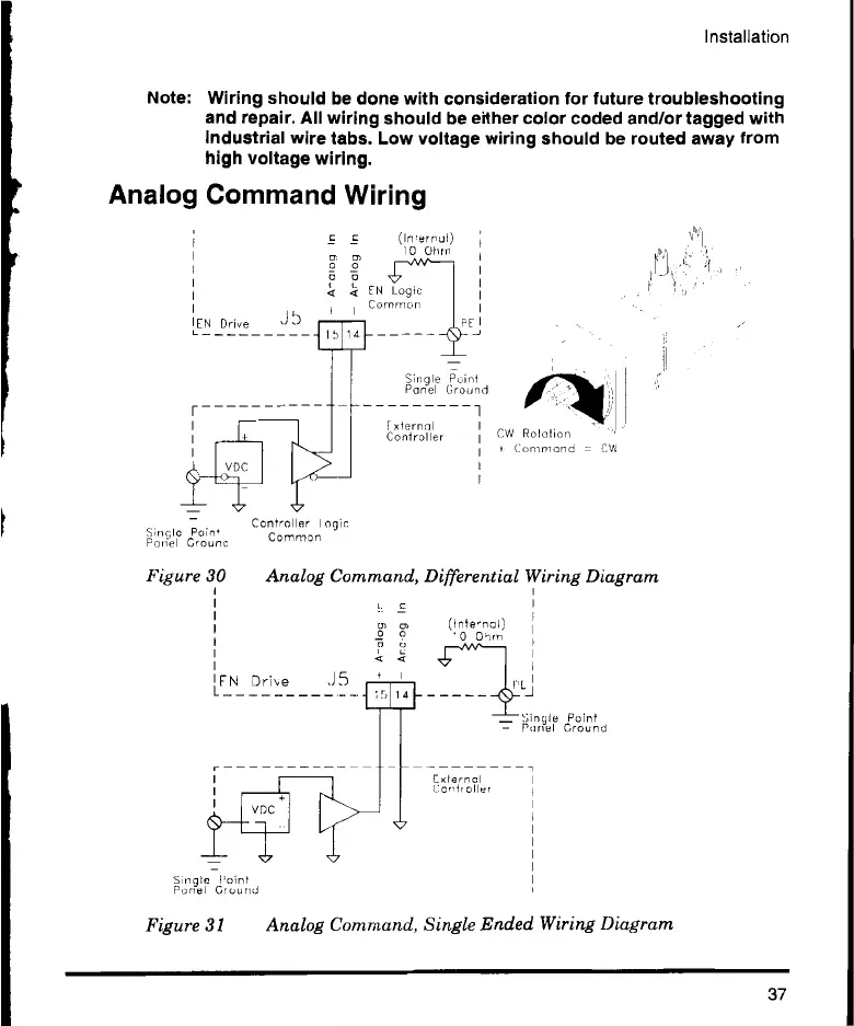
Analog Command Wiring
EN Drive
r
Sin le Poin'
Panel Crow,:
E E (Imernul)
10 Ohrn
P
5 O
:4 EN Logic
Common
Controller I °gin,
Common
FE
Single Point
Panel Ground
xternal
Controller
1
CW Relation
Command = CW
Figure 30 Analog Command, Differential Wiring Diagram
O1 Or
FN Drive J5
Panel
inl
n?l ' Ground
(Inte,nal)
0 Ohm
External
oiler
- Si mot n Ground
- Parrot
Figure
Figure 31 Analog Command, Single Ended Wiring Diagram
37
 Loading...