Installation
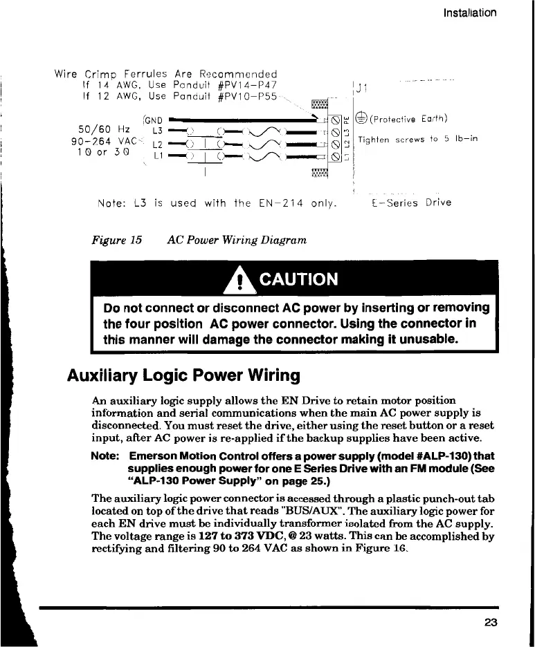
Wire Crimp Ferrules Are Recommended
If 14 AWG, Use Panduit #PV14-1347
If 12 AWG, Use Panduit #PV10-P55-
iGND
50/60 Hz L3 '
90-264 VAC L2 —.{) I (
1 0 or 3 0 L1 I 0--
e(Protective Earth)
Tighten screws to 5 lb—in
Note: L3 is used with the EN-214 only. E-Series Drive
Figure 15 AC Power Wiring Diagram
A CAUTION
Do not connect or disconnect AC power by inserting or removing
the four position AC power connector. Using the connector in
this manner will damage the connector making it unusable.
Auxiliary Logic Power Wiring
An auxiliary logic supply allows the EN Drive to retain motor position
information and serial communications when the main AC power supply is
disconnected. You must reset the drive, either using the reset button or a reset
input, after AC power is re-applied if the backup supplies have been active.
Note: Emerson Motion Control offers a power supply (model #ALP-130) that
supplies enough power for one E Series Drive with an FM module (See
"ALP-130 Power Supply" on page 25.)
The auxiliary logic power connector is accessed through a plastic punch-out tab
located on top of the drive that reads "BUS/AUX". The auxiliary logic power for
each EN drive must be individually transformer isolated from the AC supply.
The voltage range is 127 to 373 VDC, @ 23 watts. This can be accomplished by
rectifying and filtering 90 to 264 VAC as shown in Figure 16.
23
 Loading...