CC-100 Case Controllers Input and Output Setup • 9-17
tions.
The Hand-held Terminal jack also doubles as a service
pin, used when commissioning a CC-100. Plugging the
Hand-held Terminal into a CC-100 sends the special Eche-
lon ID number to the E2.
9.3.2 Power Module Wiring
CC-100s are powered by 24VAC Class 2 power, which
is supplied by a Emerson Retail Solutions power module.
The case power module should be connected
to either a
120 VAC or 240 VAC single phase power source (which-
ever is necessary for the model ordered
). Complete wiring
of the case controller power module, including lights, fans,
defrost, and anti-sweat heaters, is diagrammed in Figure
9-16. Follow all local, NEC, and UL
wiring practices.
Power is supplied to the CC-100 via the output cable
harness.
Figure 9-16
- Case Controller and Defrost Power Module
Wiring Schematic
9.3.3 Valve Cable
The six-pin connector on the right-hand side of the
CC-100 is where the liquid stepper or suction stepper must
be connected. The CC-100 uses this connection to control
the stepper motors and change the position of the valve
aperture.
All valve cable harnesses have a six-pin male connec-
tor that plugs into the CC-100’s VALVE port. Plug this
connector
in so that the tab on the top of the connector is
facing up.
For instructions on connecting the valve
cable to the
pulse or stepper valve, refer to the instructions below for
the appropriate cable type.
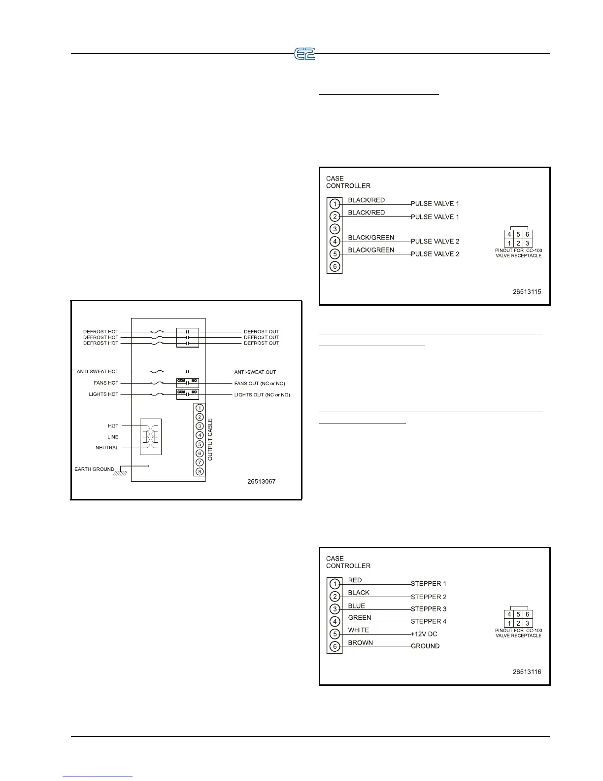
P/N 335-3263 (Pulse Valve)
Figure 9-17 shows the connections for pulse valve 1
and pulse valve 2. The pulse valve 2 leads (BLACK/
GREEN)
may be clipped if a second evaporator is not
present on the case.
Figure 9-17 - Wiring the 335-3263 Valve Cable
P/N 335-3261 (Sporlan SEI and Emerson Flow Con-
trols ESR Stepper Valve)
The 335-3261 valve cable is equipped with a four-pin
male connector that plugs into a four-pin female connector
on the valve. Plug the valve cable connector into the valve
connector.
P/N 335-3260 (Generic Stepper and Emerson Flow
Controls ESV Valve)
The 335-3260 valve cable has six flying leads for con-
nection to a stepper valve. Four
of these leads connect to
the stepper motors, while the other two serve as the power
wiring (+12VDC and ground).
The pinout for this valve cable is shown in
Figure 9-18. Table 9-5 shows how to hook the flying leads
to Emerson Flow Controls ESR, Emerson Flow Controls
ESV
, and Sporlan SEI & CDS valves.
Figure 9-18
- Wiring the 335-3260 Generic Stepper Valve