Setting up the E2 E2 Hardware Setup • 4-1
4 E2 Hardware Setup
4.1 Setting up the E2
4.1.1 Enclosure
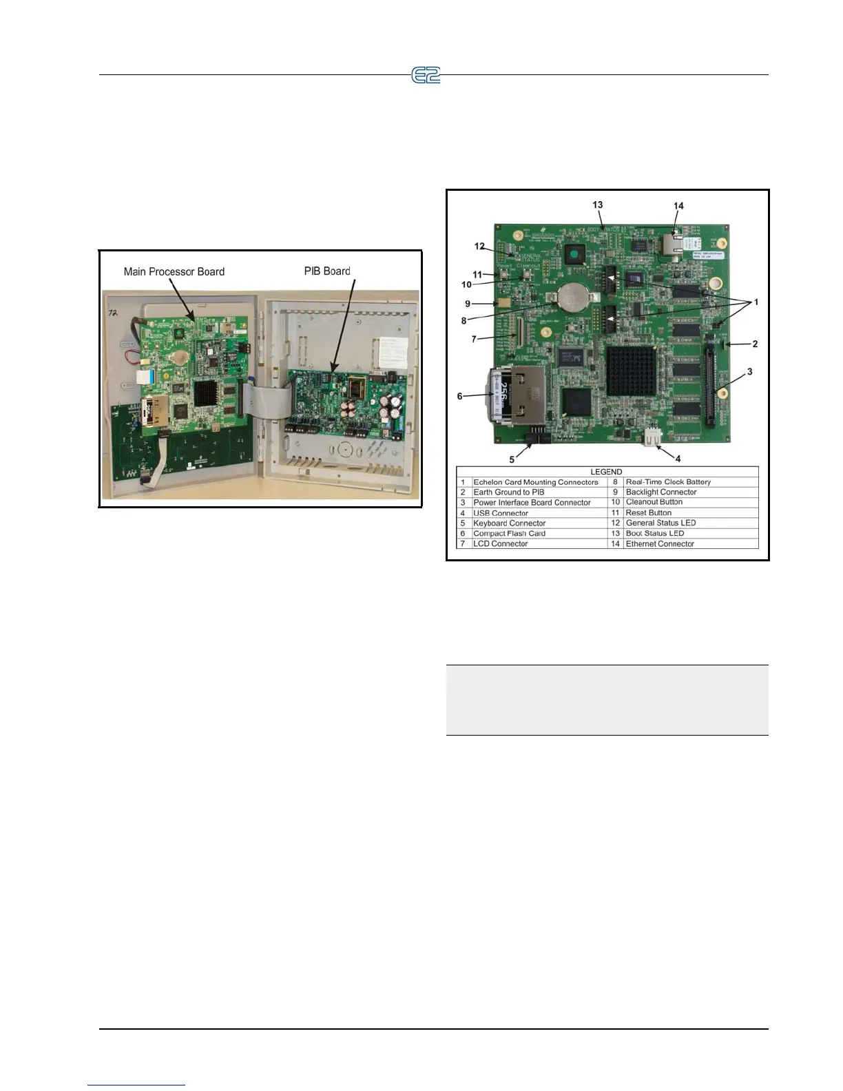
Figure 4-1 - E2 Inside Enclosure
Open the door and expose the main processor board.
The main processor board and power interface board (PIB)
are mounted side by side, one on each side of the box
enclosure.
Note that the door of the E2 controller
is not compati-
ble with the previous E2 version. The e
nclosure doors are
not interchangeable.
4.1.2 Main Processor Board
Figure 4-2 - E2 Main Board
The main processor board is mounted on the hinged
door part of the enclosure, directly behind the keyboard.
NOTE: E2 enclosure doors are not backwards com-
patible between E2 units version 3.xx and below and
units that are versi
on 4.0 and above. Keep each unit’s
door with its correct case.