Sensors and Transducers Mounting • 3-7
3.5 Sensors and
Transducers
3.5.1 Pressure Transducers
Emerson Retail Solutions transducers convert pressure
readings to proportional electrical signals between 0.5 and
4.5 volts. The transducer is designed with a 1/8-inch male
FPT fitting for connection to a standard access fitting. If
the fitting is configured with a Schrader valve, this fitting
will have to be removed and replaced with a 1/8-inch
female fitting. Each pressure transducer is supplied with
20 feet of cable for connection to a 16AI input board.
3.5.1.1 Mounting
The pressure transducers should be mounted in a verti-
cal position (pressure port down) above crank case oil
level
to prevent drainage of oil into transducer port.
3.5.2 Inside Temperature Sensor
3.5.2.1 Location
Inside temperature sensors are supplied within a wall-
mounted enclosure for attachment to a standard switch
plate.
The temperature sensor should be located in a
central
location—within the zone to be measured—away from
doors, windows, vents, heaters, and outside walls that
could affect temperature readings. In addition, the sensor
should not be mounted above other sensors that generate
heat during operation (such as relative humidity sensors).
The indoor temperature sensor should be between four
and six feet
from the floor.
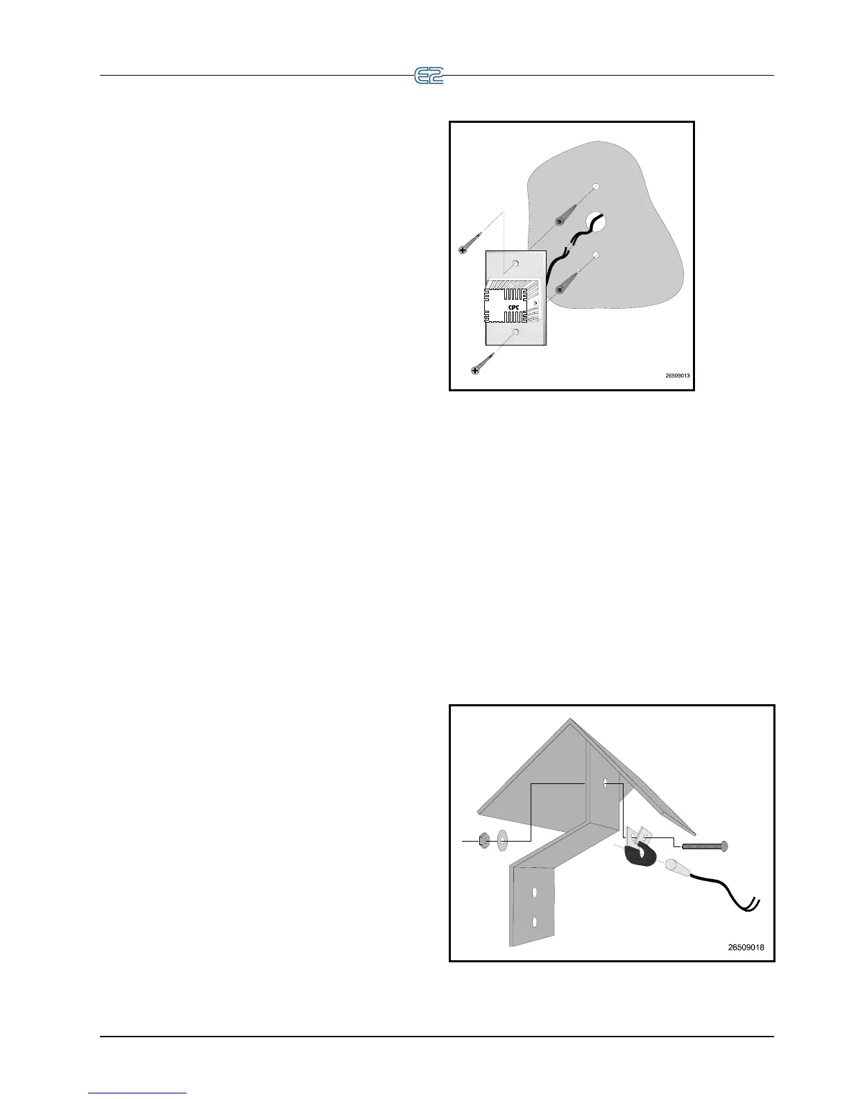
3.5.2.2 Mounting
Mount the sensor using the screws provided as shown
in Figure 3-19.
Figure 3-19
- Inside Temperature Sensor Mounting
3.5.3 Outside Temperature
Sensor
3.5.3.1 Location
The outside or ambient temperature sensor should be
located on the north side of the building, preferably under
an eave to prevent sun-heated air from affecting the tem-
perature of the sensor.
3.5.3.2 Mounting
The temperature sensor may be mounted using any
standard tubing clamp. Emerson Retail Solutions also
offers an aluminum cover and clamp (P/N 303-1111)
which may be mounted as shown in Figure 3-20 (fasteners
are not provided).
Figure 3-20
- Outside Temperature Sensor with Cover and
Clamp