CAUTION: If you change any dip switch
settings while the board is powered, disconnect
the power and re-power the board to reset.
WIRING FOR 640-0056, 56VA Transformer,
and 640-0080, 80VA Transformer
24VAC Center-Tapped Transformer
PRIMARY SIDE
240 208
C
120
(
N
E
U
T
R
A
L
)
(
H
O
T
)
120/208/240 VAC
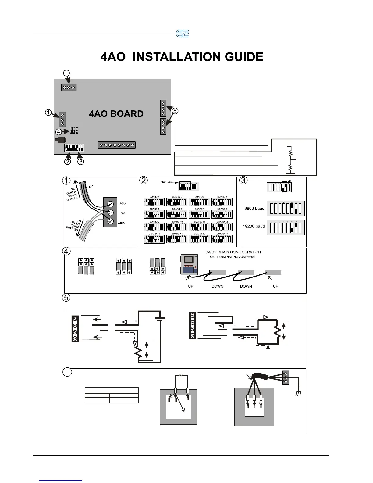
Three-conductor non-shielded cables
are the recommended wire
for connecting between the
center-tapped transformer
and I/O boards.
Power Wiring Types:
14 AWG Belden 9495
18 AWG Belden 9493
SECONDARY SIDE
24V CT 24V
AC1
0V
AC2
SHIELDED TWISTED PAIR
BELDEN #8761. FOR PLENUM,
USE BELDEN #82761 OR #88761
OR EQUIV.
WIRE + to + (same color)
WIRE 0V to 0V
WIRE - to - (same color)
BAUD RATE
1. Connect the 4AO board to the RS485 I/O Network.
2. Set the network address on the first five
rockers of dip switch S1.
3. Set the network baud rate using rockers 6
and 7 of dip switch S1.
4. If the E2 is the beginning of all RS-485 I/O or MODBUS
Networks, set all three jumpersto the UP position. For MODBUS,
set thejumpers in the top-most position (MOD). ForI/O Net, set the
jumpers in the middle position(I/O). For no termination, set the
jumpers tothe DOWN position (NO).
5. Optionally, connect the 4-20mA outputs in either a 2-wire
or 4-wire hookup as illustrated in Step 5, or if a 4-20mA is
not used, it may be left unconnected.
6. Connect board to the 24VAC secondary
of the power transformer.
center-tapped
:
Either the “2-wire” or “4-wire”
Hookup may be used at either
4-20mA output. The Hookups may
be the same or different. If a 4-20mA
is not used, it may be left unconnected.
“2-wire” 4-20mA
(Externally Powered)
Hookup example.
(Isolated)
+12V
+4-20
4-20 OUT
0V
+
+
_
_
24V
1-5V
Hookup example.
(Not Isolated)
+12V
+4-20
4-20 OUT
0V
_
+
250 ohms
Jumper
Grounded
1-5V
6
6
250 ohms
+
NOTE: The voltage divide function capability
on the previous model (P/N 810-3030) 4AO board is
no longer supported. This can now be accomplished
by using two external 15-K resistors. If used with E2,
scale output range.
NOT TERMINATED TERMINATED
FOR I/O NET
MOD
I/O
NO
MOD
I/O
NO
6-18 • E2 RX/BX/CX I&O Manual 026-1614 Rev 4 5-JAN-2013