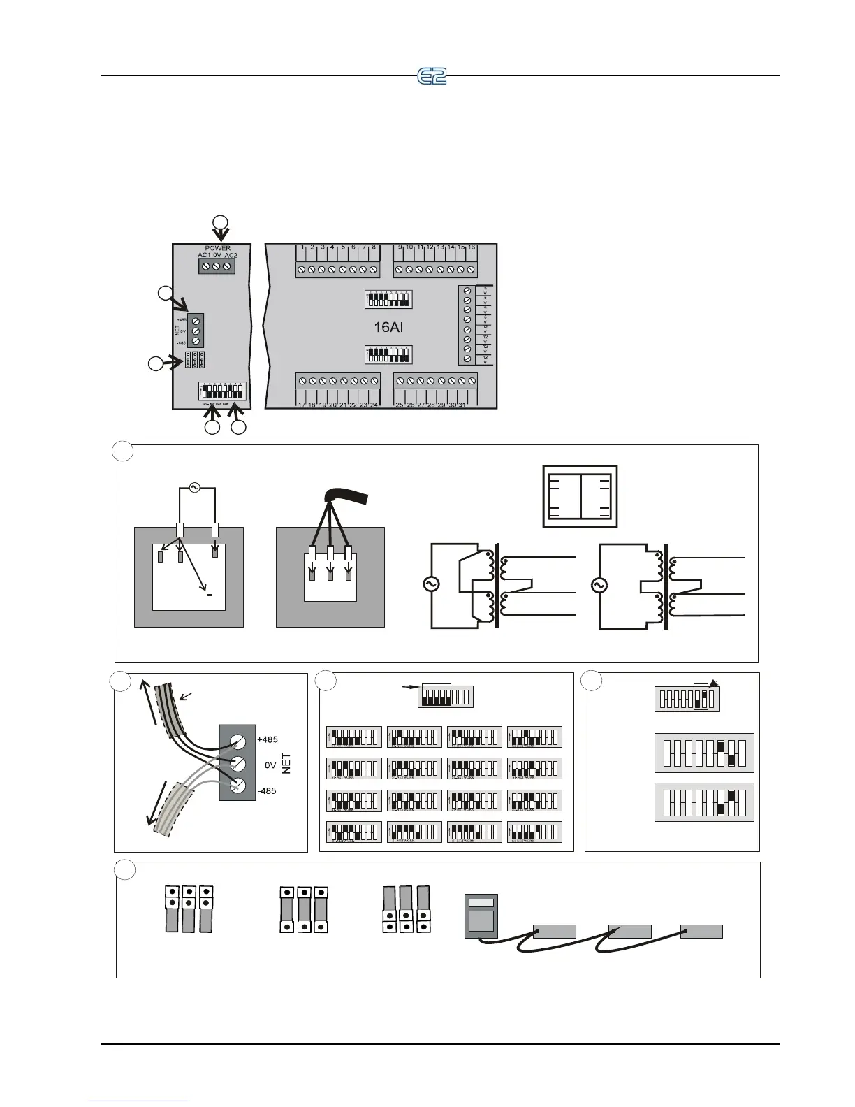
EasyManuals Logo

Emerson E2 User Manual

Emerson E2
283 pages
To Next Page IconTo Next Page
To Previous Page IconTo Previous Page
Page #77 background imageLoading...
Page #77 background image
32
2
5
34
1
1.
2. Connect 16A1 to the RS485 I/O Network.
3. Set the network address on the first five
rockers of dip switch S3.
4. Set the network baud rate using rockers 6
and 7 of dip switch S3.
5. If the E2 is the beginning of all RS-485 I/O or
MODBUS Networks, set all three jumpers to the
UP position. For MODBUS, set the jumpers in
the top-most position (MOD). For I/O Net, set the
jumpers in the middle position(I/O). For no termination,
set the jumpers tothe DOWN position (NO).
6. If you change any dip switch settings
while the board is powered, disconnect the
power and re-power the board to reset.
Connect board to power transformer.
2
SHIELDED TWISTED PAIR
BELDEN #8761
OR EQUIV.
T
O
O
T
H
E
R
R
S
48
5
D
E
V
I
C
E
S
T
O
O
T
H
E
R
R
S
4
8
5
D
E
V
I
C
E
S
WIRE + to +
WIRE 0V to 0V
WIRE - to -
3
2345678
1
ON
2345678
1
ON
2
3
4
5
6
7
8
1
ON
2345678
1
ON
2345678
1
ON
2345678
1
ON
2
3
4
5
6
7
8
1
ON
2345678
1
ON
2345678
1
ON
2345678
1
ON
2
3
4
5
6
7
8
1
ON
2345678
1
ON
2345678
1
ON
2345678
1
ON
2
3
4
5
6
7
8
1
ON
2
2
3
3
4
4
5
5
6
6
7
7
8
8
1
1
ON
BOARD 1 BOARD 2 BOARD 3
BOARD 4
BOARD 5 BOARD 6 BOARD 7
BOARD 8
BOARD 9
BOARD 10
BOARD 11
BOARD 12
BOARD 13
BOARD 14
BOARD 15
BOARD 16
ADDRESS
4
2
2
2
3
3
3
4
4
4
5
5
5
6
6
6
7
7
7
8
8
8
1
1
1
BAUD RATE
9600 baud
19200 baud
16AI INSTALLATION GUIDE
DAISY CHAIN CONFIGURATION
SET TERMINATING JUMPERS:
UP DOWN DOWN UP
5
1
WIRING FOR 640-0056, Three Board Xformer,
and 640-0080, Five Board Xformer
WIRING FOR 640-0048, Ten Board Xformer
208/230 VAC
6
5
2
1
12
11
8
7
AC1
0V
AC2
24 VAC OUTPUT
CENTER TAP
FOR 208/230 VAC POWER SOURCE
120 VAC
6
5
2
1
12
11
8
7
AC1
0V
AC2
24 VAC OUTPUT
CENTER TAP
FOR 120 VAC POWER SOURCE
PINOUT
6
2
5
1
12
8
11
7
PRIMARY SIDE SECONDARY SIDE
240 208
C
120
B
L
U
E
(
N
E
U
T
R
A
L
)
B
R
O
W
N
(
H
O
T
)
120/208/240 VAC
24V CT 24V
AC1
0V
AC2
NOT TERMINATED
TERMINATED
FOR I/O NET
MOD
I/O
NO
MOD
I/O
NO
TERMINATED
FOR MODBUS NET
MOD
I/O
NO
[
[
[
[
[
[
[
[
[
BACnet The RS485 Network and Hardware Setup • 6-21

Table of Contents

Other manuals for Emerson E2

Questions and Answers:

Question and Answer IconNeed help?

Do you have a question about the Emerson E2 and is the answer not in the manual?

Emerson E2 Specifications

General IconGeneral
ModelE2
ManufacturerEmerson
CategoryController
Power Supply24 VAC/VDC
Communication ProtocolsEthernet
Output TypeRelay, Analog
Communication ProtocolEthernet
ApplicationRefrigeration and HVAC system control

Related product manuals