Installation, Operation and Maintenance Manual
MAN-10-04-100-0711-EN Rev. 0
October 2020
21
Installation
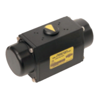
Section 4: Installation
Remove the plugs from the cable entries. For electrical connections use components
(cable glands, cables, hoses, conduits) which meet the requirements and the applicable
codes of the plant specications (mechanical protection and/or explosionproof protection).
Screw the cable glands (or the conduits) tightly into the threaded entries, in order to
guarantee the weatherproof and explosionproof protection (when applicable).
Insert the connection cables into the electrical enclosures through the cable glands (or
conduits) and, according to the wiring diagram in the main terminal board enclosure,
connect the electrical supply, the control and the signal cables to the actuator, by linking
them to the terminal blocks termination as per diagram. Replace the plastic plugs of the
unused cable entries by metal ones, to guarantee perfect weatherproof tightness and to
comply with the explosionproof protection codes (where applicable).
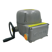
Once the connections are completed, check that the controls and signals work properly.
Two ground studs, one internal and one external, are provided to meet all local electric and
safety regulations.
Terminate the ground connections at least to the external stud marked ground.
Connect the motor supply cable previously sized in accordance with:
• The absorbed current correspondent to the actuator nominal torque with the
torque limiting device set at 100 percent
• Cable size; 1 power: 4 mm
2
/AWG12 (max) 2 controls: 1.5 mm
2
/AWG 16 (max)
• The applicable plant and safety norms
• For actuators certied according to CSA standards the eld connections shall be
done with certied crimp-on ring terminals.
 Loading...