11
3 80 4.45 113.03 4.49 114.05 4.55 115.57
4 100 5.39 136.91 5.43 137.92 5.49 139.45
6 150 7.79 197.87 7.83 198.88 7.89 200.41
8 200 9.42 239.27 9.46 240.28 9.52 241.81
10 250 11.92 302.77 11.96 303.78 12.02 305.31
12 300 13.94 354.08 13.97 354.84 14.00 355.60
14 350 15.80 401.32 15.83 402.08 15.86 402.84
16 400 17.44 442.98 17.47 443.74 17.50 444.50
18 450 19.06 484.12 19.10 485.14 19.19 487.43
20 500 21.06 534.92 21.10 535.94 21.19 538.23
24 600 26.06 661.92 26.10 662.94 26.19 665.23
26 650 28.28 718.31 28.36 720.34 28.45 722.63
30 750 32.06 814.32 32.12 815.85 32.21 818.13
36 900 38.20 970.28 38.30 972.82 38.39 975.11
42 1050 45.06 1144.52 45.19 1147.83 45.31 1150.87
48 1200 50.74 1288.80 50.77 1289.56 50.89 1292.61
54 1350 55.74 1415.80 55.77 1416.56 55.89 1419.61
60 1500 63.95 1624.33 63.99 1625.35 64.11 1628.39
CLARKSON SLURRY KNIFE GATE VALVES
KGA+
TABLE 4 - HOUSING I.D.
Valve size I.D. minimum I.D. maximum
Maximum allowable
housing I.D.
NPS DN inch mm inch mm inch mm
Reassembly
1. If valve has been removed from pipe, lift
valve to vertical position, refer to Lifting,
Section 15.
2. Using DOW III or approved alternate,
completely fill all internal cavities of the
newsecondary seal.
3. Insert the new lubricated secondary seal
into the valve housing assembly. Make sure
that the lube path openings on the seal line
up with corresponding external housing
lubrication fittings.
4. Place the secondary seal retainer plate
intoposition.
5. Replace and hand tighten all the retainer
plate fasteners and lockwashers.
6. Apply a small amount of recommended
lubricant to the two tapered faces of the
‘sharp end’ of the gate.
7. Press the gate firmly through the secondary
seal into the valve housing assembly until
the mark drawn on the gate reaches the
top of the retainer plate or gate reaches
dimension A, Table 5, Figure 13.
8. Fully tighten all the retainer plate fasteners.
9. Reinstall the actuator / frame assembly with
the housing / frame fasteners loosely.
10. Reconnect the gate to the actuator. (In order
to facilitate installation and future removal,
a coating or anti-seize compound should be
applied to the outside of the clevis pin over
the yoke contact area).
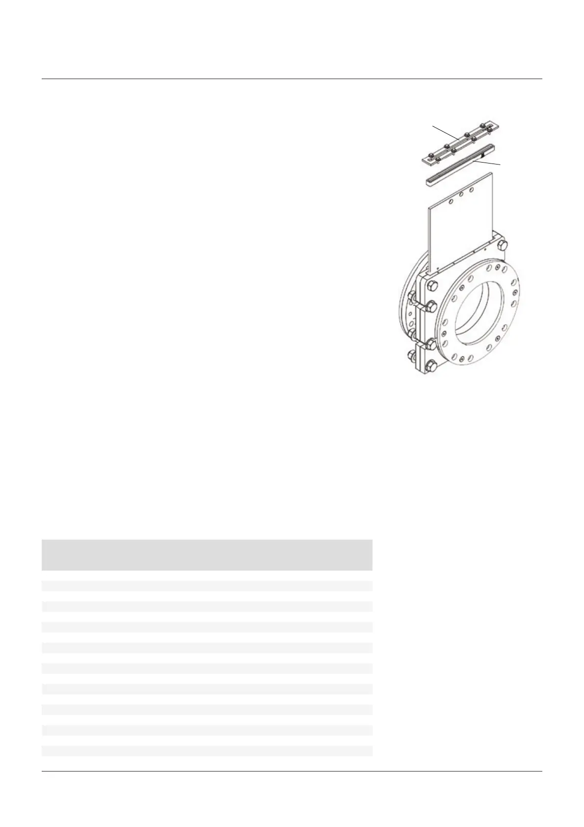
FIGURE 11
Secondary
sealretainer
Secondary
seal
11. ‘Stretch’ the frame / actuator assembly
with respect to the housing by pulling (not
lifting) the frame / actuator assembly to
its maximum movement away from the
housing assembly (holding housing in place
if valve is removed from pipeline). Tighten
the frame/ housing bolts and verify the
tightness of the actuator to frame bolts.
12. Cycle valve to full open position and check
the gate position using the data in the
Table5, Figure 13. Adjust as required.
13. Rattle the gate. It should be mostly
disengaged from the sleeves. The outboard
edges of the gate should be free and the
center still partially engaged in between
thesleeves.
14. Cycle gate full closed and full open.
15. Inspect gate for pieces of rubber. If
significant amount of rubber is present, a
sharp edge(s) on the gate may be causing
seal damage or the gate is extending too
far on the up stroke. The ends of the gate
should be free and the center still engaged.
If the sleeve / gate is misaligned, loosen the
frame actuator bolts and / or adjust the yoke
until the proper position, open and closed,
isobtained.
16. If out of pipeline, reinstall the valve, refer
toLifting, Section 15.