32
CLARKSON SLURRY KNIFE GATE VALVES
KGA
31 FIELD REPLACEMENT OF GATES
CAUTION
Since this procedure may be performed with the
valve in an active pipeline, plant standard safety
procedures must be followed. Use of personal
protective equipment, tag out or other plant
standard safety procedures must be followed.
If valve is removed for this service, assure line
is not pressurized before removing valve. Valve
assembly and parts may be heavy, use proper
lifting and support techniques, refer to Lifting,
Section 33.
1. Open the valve, so the gate is in the fully
raised position.
2. Remove the cotter pin and clevis pin from
the gate. It may be necessary to actuate
the valve down slightly in order to relieve
pressure on the clevis pin to facilitate
removal.
3. Actuator assembly removal:
Smaller valves: remove the frame to
housing bolts of one side except for the
lowest bolt on the opposite side of the
frame. This bolt will act as a pivot point for
the frame / actuator assembly. Pivot the
frame / actuator assembly away from the
valve and temporarily support.
Larger valves: remove the frame to housing
bolts. Lift the frame and actuator assembly
off the housing assembly to allow gate
removal.
4. Remove the old gate.
5. Inspect the gate for sharp edges or
excessive damage. Some scoring will
occur in normal use. If the gate has been
bent beyond
1
/
16” (1.5 mm) permanent
deflection at the center, straighten or
replace. If straightening is performed,
use considerable care to minimize marks
on gate surface. Scores or other distress
marks may be cleaned up with a belt
sander. Machining the gate surface is not
recommended. Light scale buildup may
be removed with a putty knife or gasket
scraper. Inspect the gate for wear and
roughness. Use a disc grinder or belt sander
to remove rough surfaces. Take particular
care on the leading and beveled edge to
remove burrs and other sharp edges.
6. Apply a liberal amount of recommended
lubricant to the two tapered faces of the
‘sharp end’ of the gate.
7. Press the gate into the valve housing
assembly until the mark drawn on the gate
reaches the top of the retainer plate or
gate reaches approximately dimension A,
Table5, Figure 13.
8. Reinstall the actuator / frame assembly
withthe housing / frame fasteners loosely.
9. Reconnect the gate to the actuator. (In order
to facilitate installation and future removal,
a coating or anti-seize compound should be
applied to the outside of the clevis pin over
the yoke contact area.)
10. ‘Stretch’ the frame / actuator assembly
with respect to the housing by lifting the
frame / actuator assembly to its maximum
movement up away from the housing
assembly. Tighten the frame / housing bolts
and verify the tightness of the actuator to
frame bolts.
11. Tighten all of the frame to housing bolts.
12. Test stroke the valve to verify travel and
wiper / wiper retainer interference with
the yoke. Adjust / replace the wipers as
required.
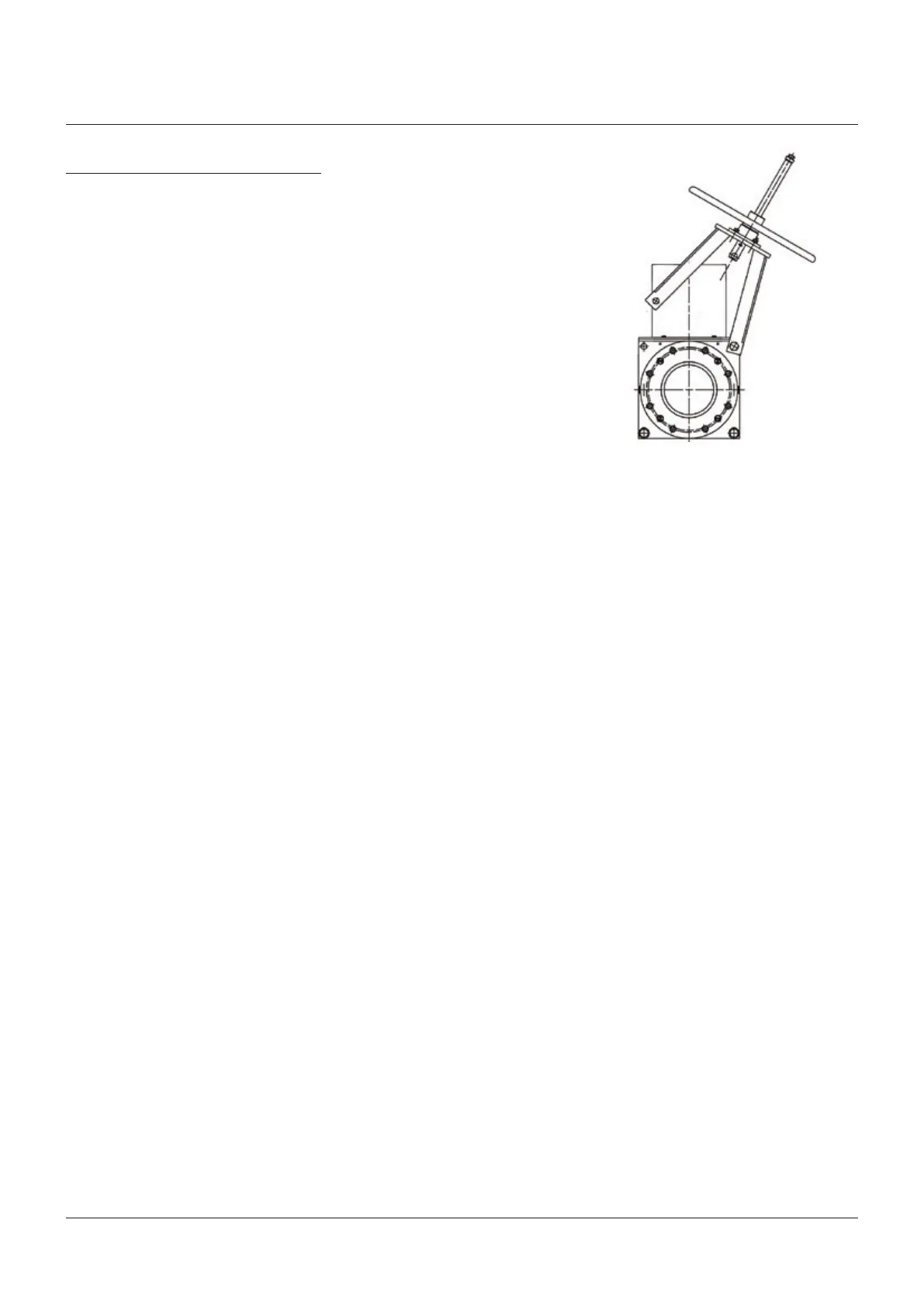
For gate replacement, smaller valves may
have the actuator frame swung out of the way
as illustrated here. Remove frame bolts on
one side only and loosen the opposite side
just enough to allow movement. Be sure and
properly support weight of actuator assembly,
taking care to avoid injury.
FIGURE 14
 Loading...


