2
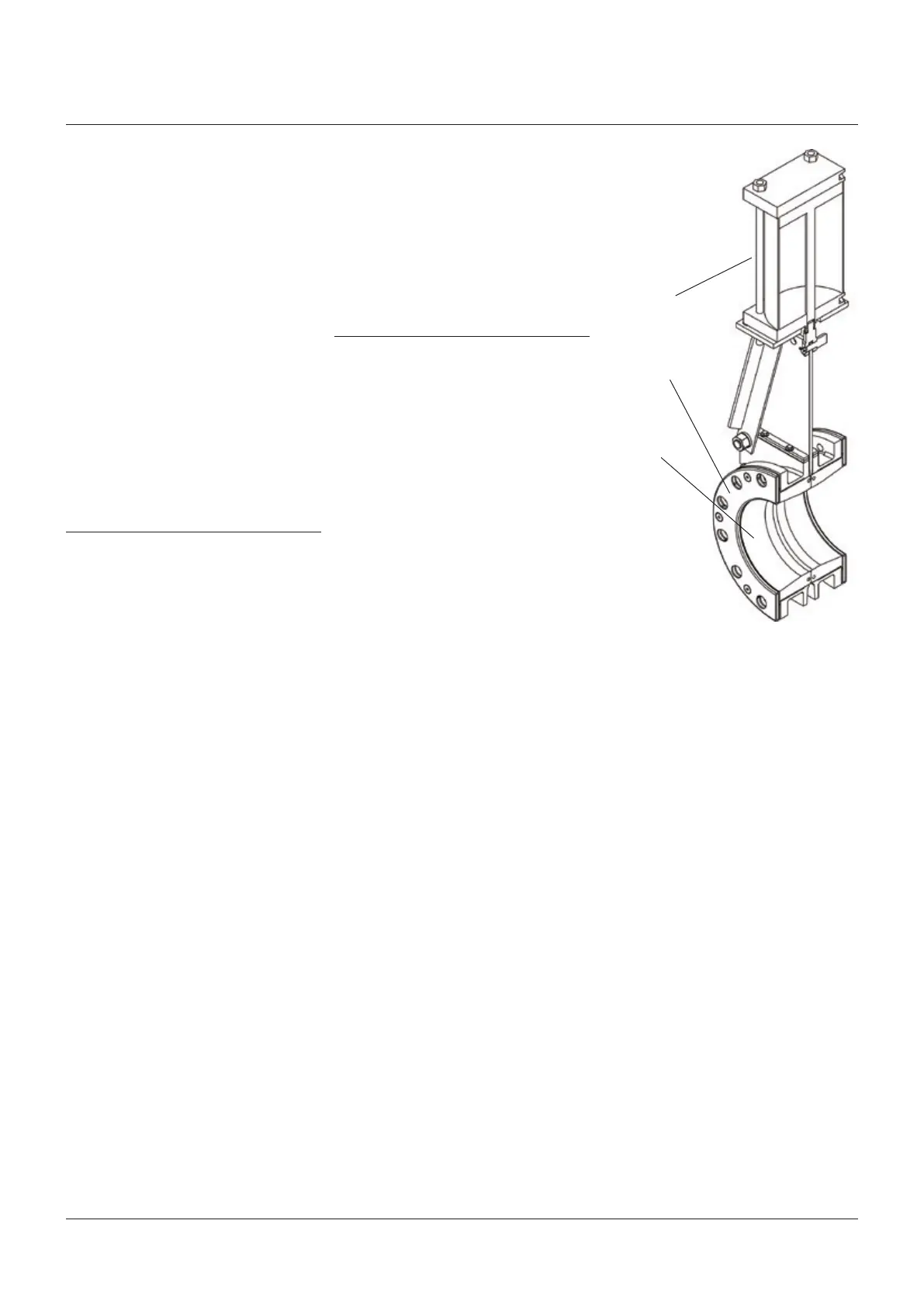
CLARKSON SLURRY KNIFE GATE VALVES
KGA+
Operators
Retainer flanges
Sleeves
FIGURE 1
2 INITIAL INSPECTION
1. Examine entire valve and report any
damageor discrepancies immediately.
2. Sleeves: visually examine the sleeves
interior, looking for chunking, irregularities
or other damage. It is not recommended you
remove the retainer flanges (if equipped).
3. Retainer flanges: sizes NPS 8 (DN 200) and
below may or may not have the optional
retainer flanges, retainer flanges are
standard on sizes NPS 10 (DN 250) and
larger. Visually examine the retainer flanges
surfaces, looking for tears, irregularities or
other damage. Check tightness of retainer
flange bolting.
4. Operators: standard manual handwheels
may be shipped loose for field installation,
be sure to fully tighten.
5. Valves are normally shipped with gate in
open position, the recommended position
for installation. Valves supplied with spring
to extend (fail close) cylinder actuators are
shipped with the gate in the closed position.
The KGA+ should be installed with the gate
in the open position, exercise caution when
applying air to open this valve and then
ensure that it is locked in the open position
when installing in the line.
6. Accessories: if provided, including
solenoids, limit switches, positioners,
etc., are tested for functionality prior to
shipment. Examine carefully for damage
which may occur during shipment.
1 GENERAL INFORMATION
1. The KGA+ is a packingless, slurry knife
gate valve. All the sealing is accomplished
by the elastomeric sleeves in the valve
housing. The sleeves also form the wear
section for the valve. The gate is removable
for inspection or replacement while the
valveisin service.
2. The KGA+ is BIDIRECTIONAL
(two-way shut-off) product and can be
installed without concern over direction of
flow. Since they will shut-off equally with
in either direction, you will find no arrows
or other indicators of a direction of flow or
seatside.
3. Clarkson slurry knife gate valves are
suitable for on-off service only. They are
notto be used in a throttling application.
4. The style, size, pressure rating and material
selection are the responsibility of the piping
system designer.
Secondary seal: the KGA utilizes a multipart
gate wiper assembly to wipe the gate and
reduce potential for discharge from the top of
the valve where the gate enters the housing
assembly. The KGA+ features a secondary seal
assembly capable of being lubricated without
disassembly. Similar to what is currently
offered on the KGD; this new seal design
incorporates an external lubrication fitting to
directly inject lubrication into the seal’s interior
(patent pending).
Simplified housing assembly: housing spacers
found on the KGA have been eliminated from
the KGA+ allowing for an easier disassembly /
assembly process.
With these changes, spare parts and
interchangeability with the prior design have
been impacted. These changes are detailed
inSections ‘Spare parts’ (KGA+ and KGA).
5. All valves should be operated within the
design pressure and temperature ranges.
Under no circumstances should the valves
be operated at conditions outside these
parameters. Do not exceed 100% of the
maximum pressure rating of the valve at
anytime during its operation. Pressure
spikes beyond the valve’s pressure rating
are solely the responsibility of the user.