34
3 80 50 22.7 127 57.6 85 38.6 50 22.7
4 100 64 29.0 141 64.0 130 59.0 70 31.8
6 150 98 44.5 175 79.4 180 81.6 98 44.5
8 200 135 61.2 212 96.2 210 95.3 135 61.2
10 250 198 89.8 275 124.7 310 140.6 175 79.4
12 300 - - 427 193.7 669 303.5 360 163.3
14 350 - - 448 203.2 720 326.6 414 187.8
16 400 - - 573 259.9 1125 510.3 550 249.5
18 450 - - 875 396.9 1330 603.3 950 430.9
20 500 - - 1054 478.1 1680 762.0 1200 544.3
24 600 - - - - 2200 997.9 1400 635.0
26 650 - - - - - - 1700 771.1
30 750 - - - - - - 2150 975.2
36 900 - - - - - - 3500 1587.6
42 1050 - - - - - - 5200 2358.7
48 1200 - - - - - - 6970 3161.5
54 1350 - - - - - - 8275 3753.5
60 1500 - - - - - - 9500 4309.1
CLARKSON SLURRY KNIFE GATE VALVES
KGA
33 LIFTING
CAUTION
Valve assembly and parts may be heavy, use
proper lifting and support techniques. DO NOT
attempt to lift valve together with any adjoining
pipe or other equipment. DO NOT attempt to lift
valve if full of media. Lifting techniques may vary
depending on valve size/weight. Small Clarkson
KGA air and or hydraulic actuated valves may be
equipped with eyebolts. These may only be used
as lifting points on valve sizes NPS 10 (DN 250)
and smaller for lifting valve and actuator ONLY.
DO NOT Use these eyebolts on any larger valve.
For shipment, large KGA valves are normally
palletized in the flat or horizontal position with
the bore oriented vertically, flange faces down
on pallet. The palletized valves are loaded on
to trucks with a forklift. It is recommended
unloading should also be done with a forklift.
A crane can be used; however the weight must
be supported by the pallet and not the valve.
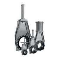
For KGA valves with slotted flanges, DO NOT
lift or attempt to move valve with straps placed
around the lugs of the mounting flanges, this is
very dangerous.
Small Clarkson KGA air and or hydraulic
actuated valves may be equipped with eyebolts.
Illustration is for reference and not intended
to show a recommended lifting apparatus.
Be sure and follow proper lifting and support
techniques.
FIGURE 16
DO NOT use flange lugs to lift valve
These should only be used on valve sizes
NPS 10 (DN 250) and smaller to lift valve and
actuator assembly ONLY. Insert a properly
rated strap and or lifting hook through eye of
eyebolt and lift, taking care as center of gravity
shifts. Do not drag the base of the valve during
lifting as this can peel the rubber from the
retaining flanges.
All valves can be lifted using the frame (yoke)
assembly as the lift point. DO NOT USE
LOCKOUT BRACKETS TO LIFT VALVE. Insert
properly rated straps under the frame top plate,
one for each leg, and lift, taking care as center
of gravity shifts. Do not drag the base of the
valve during lifting as this can peel the rubber
from the retaining flanges.
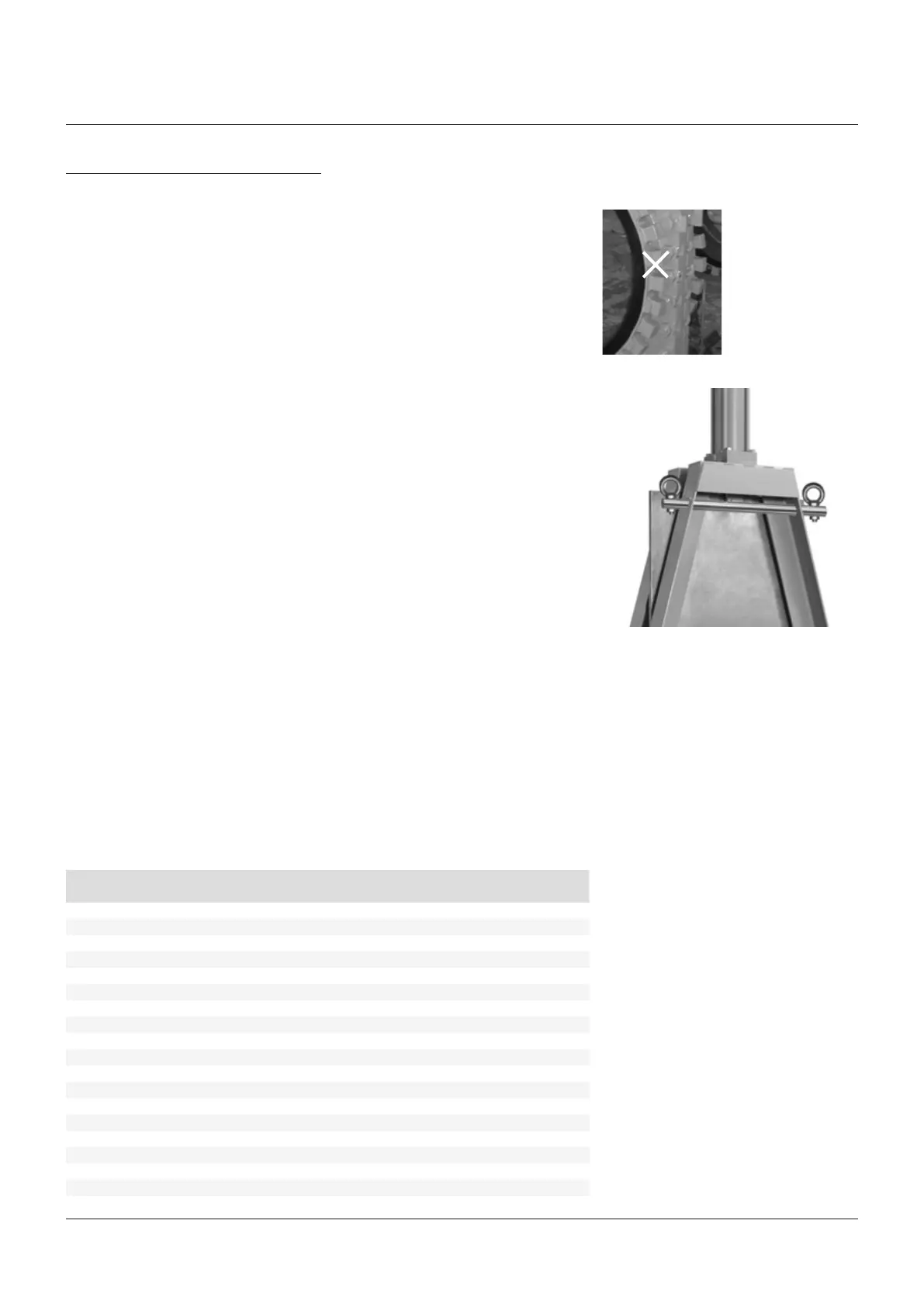
Some larger KGA valves can be lifted using
the lifting holes located near the top of each
frame leg, on the side. DO NOT USE LOCKOUT
BRACKETS TO LIFT VALVE. Appropriately sized
and rated hoist rings can be placed in the lifting
holes. Alternatively, two appropriately sized and
rated steel bars can be slid through the holes
and hoist rings threaded into the ends (see
photo for a typical arrangement). For larger
valves, all lifting should be done with chains.
Shackles and straps, regardless of their weight
ratings should never be used. Take care to not
drag the base of the valve during lifting as this
can peel the rubber from the sleeve retaining
flanges.
FIGURE 17
TABLE 6 - STANDARD VALVE ASSEMBLY WEIGHTS
Valve size MH BG AC HC
NPS DN lbs kg lbs kg lbs kg lbs kg