3
3 80 37 50
4 100 37 50
6 150 69 93
8 200 69 93
10 250 113 153
12 300 113 153
14 350 169 229
16 400 169 229
18 450 238 322
20 500 238 322
24 600 345 467
26 650 345 467
30 750 345 467
36 900 610 827
42 1050 610 827
48 1200 610 877
54 1350 1000 1355
60 1500 1000 1355
3 80 25 34
4 100 25 34
6 150 40 54
8 200 40 54
10 250 65 88
12 300 65 88
14 350 100 135
16 400 100 135
18 450 140 190
20 500 140 190
24 600 200 271
26 650 200 271
30 750 200 271
36 900 320 434
42 1050 320 434
48 1200 320 434
54 1350 600 443
60 1500 600 813
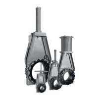
CLARKSON SLURRY KNIFE GATE VALVES
KGA+
TABLE 1 - MAXIMUM TIGHTENING TORQUESTANDARD FLANGES
Valve size
ft·lb N·mNPS DN
TABLE 2 - MAXIMUM TIGHTENING TORQUE FRP FLANGES
Valve size
ft·lb N·mNPS DN
Installation notes
A) All slurry knife gate valves are designed and
manufactured to be installed in applications
where no more than 1 g of force in excess
of gravity is applied to the valve in any
direction. This 1 g force can be an effect
of traffic, wind, or earthquake, etc. Valves
should not be used in applications that
exceed 1 g.
B) If valve stem or topworks protrude into
walkways or work areas, valve should be
flagged per company safety policy.
C) All piping systems should contain
independent support mechanisms and
should not utilize the valve as a sole
meansof support.
D) Do not install valve over walkways, electrical
or other critical equipment without the use
of splash guards or similar considerations.
2. The mating line flanges must be properly
aligned prior to attempting installation. Slip
on or weld flanges can be used. Never try to
make up for misaligned pipe flanges by the
line bolting. Pipe supports and/or expansion
joints should be used to minimize pipe
loads on valves. The pipeline companion
flanges should be raised or flat face type to
insure full sleeve support and a continuous
unvarying I.D. If slip-on flanges are used,
the pipe should be cut square and welded in
position with the pipe end matched evenly
with the flange face. Studded flanges are not
compatible with these valves. Tables 1 and2
state the maximum flange bolt tightening
torques. Listed in Table 3 are the fasteners
required for installation.
3. Sizes NPS 8 (DN 200) and below may or
may not have the optional retainer flanges.
Retainer flanges are standard on sizes
3 INSTALLATION INSTRUCTIONS
Please take note of the specific installation
tagsprovided with each valve.
1. The KGA+ is installed with the gate in the
fully open position with the sleeves inserted
into the housing halves.
CAUTION
Valves are normally shipped with gate in
open position, the recommended position for
installation. Valves supplied with spring to extend
(fail close) cylinder actuators are shipped with
the gate in the closed position. Gate should be
actuated to the open position prior to installation,
exercise extreme caution when applying air
to open this valve and then ensure that it gate
lockedin the open position for installation.
NPS 10 (DN 250) and larger. Ifnoretainer
flanges are used, the flanged end of the
sleeves form the gasket when installed
into the pipeline. When equipped with
retainer flanges, the elastomer coated
retainer flange functions as the gasket
forinstallation into the pipeline.
4. Valve is suitable for use in either vertical or
horizontal lines. The valve can be installed
in any position in vertical or horizontal
pipelines. However, valves installed in
an orientation with the actuator below
horizontal may require flushing to prevent
the buildup of solids in the housing and may
require additional actuator support.
5. Standard mating flanges NPS 3 - 24
(DN 80 - 600) match ASME B16.5/150,
sizesNPS 26 (DN 650) and largerare per
MSS-SP44 (see Table 1).