33
CLARKSON SLURRY KNIFE GATE VALVES
KGA
Note: it is normal for the KGA to discharge
media during opening and closing cycles.
This helps prevent any solids from building up
between the sleeves that would prevent a tight
seal when the valve is fully open or closed.
Discharge can be controlled with the use of an
optional splash guard or drain plate. Do not
install valve over walkways, electrical or other
critical equipment without the use of splash
guards, drain plates or similar considerations.
32 INSTALLATION INSTRUCTIONS FOR
SPLASH GUARD (B7 OPTION)
1. Remove the splash guard, mounting
hardware, and gasket from the valve crate.
Verify that the proper number of mounting
U-bolts, washers, nuts, along with the
guard, end cap, and gasket material are
present.
13. ‘Stretch’ the frame / actuator assembly
with respect to the housing by pulling (not
lifting) the frame /actuator assembly to
its maximum movement away from the
housing assembly (holding housing in place
if valve is removed from pipeline). Tighten
the frame/ housing bolts and verify the
tightness of the actuator to frame bolts.
14. Cycle valve to full open position and check
the gate position using the data in the
Table5, Figure 13. Adjust as required.
15. Rattle the gate. It should be mostly
disengaged from the sleeves. The outboard
edges of the gate should be free and the
center still partially engaged in between
thesleeves.
16. Cycle gate full closed and full open.
17. Inspect wipers and wiper retainers, replace
as required (see Section 29).
18. Inspect gate for pieces of rubber. If
significant amount of rubber is present, a
sharp edge(s) on the gate may be causing
seal damage or the gate is extending too
far on the up stroke. The ends of the gate
should be free and the center still engaged.
If the sleeve / gate is misaligned, loosen the
frame actuator bolts and / or adjust the yoke
until the proper position, open and closed,
isobtained.
19. If out of pipeline, reinstall the valve, refer
toLifting section.
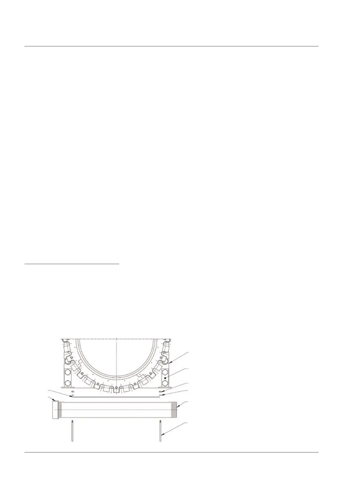
Housing
Bracket
Hex nut
Lockwasher
Splash guard
U-bolt
FIGURE 15
Gasket
Cap
(one only, do
not cap both
ends)
2. Cut the gasket material into four pieces
that will form the rectangular dimensions
of the bottom of the valve if adhesive back
strip is used. If the gasket is cut from
sheet elastomer stock, ¼" (6.4 mm) thick
material is recommended. Material should
be compatible with the slurry chemistry.
The material used for the retainer flanges
or sleeves will be suitable for the B7 gasket.
Other choices may be possible. Consult the
factory for recommendations.
3. Clean the flat machined surface of the
splash guard so that there is no dirt, grit,
grease, or other debris present. Remove
the adhesive backing from the gasket
material and apply to the splash guard on
the machined flat mating surface (adhesive
back strip). If a cut sheet gasket is used, it
should be attached to the splash guard with
an RTV type adhesive compound to hold it
during installation. Attach gasket material
to the flat surface along the edge of the
machined slot.
4. Install the pipe cap on one end of the splash
guard.
5. Position the guard below the valve and fit
a U-bolt on each end with the fasteners
loosely attached.
6. Verify the position of the gasket material
and the bottom of the housing and tighten
the installed U-bolts.
7. Tighten all U-bolt fasteners until the gasket
is visually compressed.
WARNING!
Do not cap or close-off both ends of the splash
guard. This can result in valve failure.