27
CLARKSON SLURRY KNIFE GATE VALVES
KGA
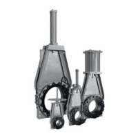
FIGURE 828 SLEEVE REPLACEMENT
Note: sizes NPS 8 (DN 200) and below may
or may not have the optional retainer flanges.
Retainer flanges are standard on sizes NPS 10
(DN 250) and larger. Larger diameter valves are
supplied with segmented (multipart) retainer
flanges. If your valve has segmented retainer
flanges, take note of the special sections.
Inspection of components
1. Verify that for each valve there are two(2)
sleeves, two (2) retainer flanges (if required),
retainer flange bolts and nuts (if required).
KGA NPS 30 - 60 (DN 750 - 1500), use
segmented retainer flanges. Refer to
the Clarkson certified parts list for the
appropriate valve size to determine the
quantity of retainer flange nuts and bolts
required.
2. Visually inspect each sleeve and retainer
flange for damage to surfaces resulting
from shipping or post-shipping handling.
The sealing surfaces (nose) must be free
ofdepressions, slits or gouges.
Disassembly
1. Before working on the KGA valve, verify that
the valve is in the open position. If it isnot,
move it to the open position.
CAUTION
Assure line is not pressurized before removing
valve. Valve assembly and parts may be heavy,
use proper lifting and support techniques.
SeeSection33, Lifting.
2. Remove the valve from the piping.
3. Visually inspect and verify that the sleeve
bore is clear of all debris, scale and
elastomer residue.
4. Remove the retainer flange bolts taking
caution to prevent retainer flanges from
falling free if in vertical position. Remove
theretainer flanges from the valve.
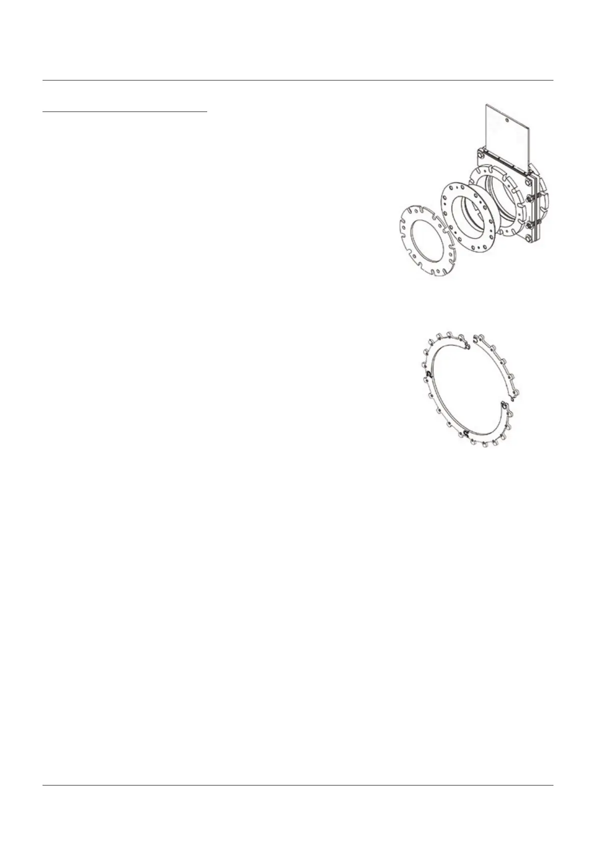
5. For valves with segmented retainer flanges
(see Figure 9), loosen retainer bolts and pull
each individual segment straight up away
from the valve, do not remove more than
one section at a time.
Installation
1. Lay valve down in a horizontal position, on
a flat surface. (While it is possible to install
valve sleeves with assembly in vertical
position, this may make it more difficult
to properly align the retainer flanges and
sleeves, especially on larger valves.)
2. Check the bore diameter for unusual or
excessive wear. If found, valve housing
mayrequire replacement.
3. Table 4 shows the maximum / minimum
bore dimensions of a new KGA valve, along
with the maximum allowable diameter
figures of a housing affected by wear and
usage. If housing is not within the maximum
allowable range, it is recommended that the
housing be replaced before installing new
sleeves. In some cases, it may be possible to
make minor repairs to the housing in order
to continue using it. Please contact the
factory for information.
4. Lubricate the O.D. of the seal end of
thesleeve.
5. Install the sleeve, being careful to center
theflange end in the bore of the housing.
6. Place a retainer flange on the top of the
sleeve. Align the retainer flange bolt holes
with the matching holes in the round
flange. Align the I.D. of the sleeve and
retainerflange.
7. For valves with segmented retainer flanges,
position one retainer flange segment on the
sleeve lip. Align with proper mounting holes
in the round flange. Install the required
bolts and nuts; hand tight. Position the next
segment on the sleeve lip opposite the one
previously installed. Install fasteners as
before. Continue to install segments in this
manner until complete flange is in position.
6. Remove the two elastomer sleeves by
simply pulling each sleeve out of the
housing assembly. (Sometimes a putty knife,
large screwdriver or pry bar is necessary to
pry the retainer flange away from the sleeve
and the sleeve from the valve flange.)
FIGURE 9
Example of a segmented retainer