31
‘A’
‘B’
3 80 1.59 40.39 5.22 132.59
4 100 1.53 38.86 6.28 159.51
6 150 1.52 38.61 8.77 222.76
8 200 1.59 40.39 10.59 268.99
10 250 1.46 37.08 12.59 319.79
12 300 2.12 53.85 15.30 388.62
14 350 2.18 55.37 17.18 436.37
16 400 2.44 61.98 19.82 503.43
18 450 5.06 128.52 24.31 617.47
20 500 4.26 108.20 26.01 660.65
24 600 5.34 135.64 32.34 821.44
26 650 4.00 101.60 33.00 838.20
30 750 4.75 120.65 37.75 958.85
36 900 4.75 120.65 43.75 1111.25
42 1050 6.62 168.15 52.62 1336.55
48 1200 6.49 164.85 58.00 1473.20
54 1350 5.73 145.54 63.23 1606.04
60 1500 8.00 203.20 70.50 1790.70
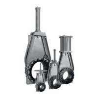
CLARKSON SLURRY KNIFE GATE VALVES
KGA
TABLE 5
Valve size ‘A’ ‘B’
NPS DN inch mm inch mm
Dimensional tolerance:
NPS 3 - 10 (DN 80 - 250) +/-
1
/
16 (1.5 mm)
NPS 12 - 16 (DN 300 - 400) +/-
3
/
32” (2.4 mm)
NPS 18 - 26 (DN 450 - 650) +/-⅛” (3 mm)
NPS 30 - 60 (DN 750 - 1500) +/-¼” (6 mm)
Dimension A = Distance from top of valve
housing (not wiper plate) to top
of gate in the closed position.
Dimension B = Distance from top of valve
housing (not wiper plate) to top
of gate in the opened position.
FIGURE 1310. Press the gate into the valve housing
assembly until the mark drawn on the gate
reaches the top of the retainer plate or
gate reaches approximately dimension A,
Table5, Figure 13.
11. Reinstall the actuator / frame assembly
withthe housing / frame fasteners loosely.
12. Reconnect the gate to the actuator. (In order
to facilitate installation and future removal,
a coating or anti-seize compound should be
applied to the outside of the clevis pin over
the yoke contact area).
13. 'Stretch' the frame / actuator assembly
with respect to the housing by pulling (not
lifting) the frame /actuator assembly to
its maximum movement away from the
housing assembly (holding housing in place
if valve is removed from pipeline). Tighten
the frame/ housing bolts and verify the
tightness of the actuator to frame bolts.
14. Cycle valve to full open position and check
the gate position using the data in the
Table5, Figure 13. Adjust as required.
15. Rattle the gate. It should be mostly
disengaged from the sleeves. The outboard
edges of the gate should be free and the
center still partially engaged in between
thesleeves.
16. Cycle gate full closed and full open.
17. Install wipers and wiper retainers on each
side of the gate.
18. Inspect gate for pieces of rubber. If
significant amount of rubber is present, a
sharp edge(s) on the gate may be causing
seal damage or the gate is extending too
far on the up stroke. The ends of the gate
should be free and the center still engaged.
If the sleeve / gate is misaligned, loosen the
frame actuator bolts and / or adjust the yoke
until the proper position, open and closed, is
obtained.
19. If out of pipeline, reinstall the valve, refer to
Lifting section.
 Loading...


