30
CLARKSON SLURRY KNIFE GATE VALVES
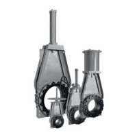
KGA
Gate
Wiper retainer w/bolts
Wiper
Housing bolts
Retainer flange
Housing
Spacer bar
Sleeve
Retainer flange bolts
FIGURE 12
Reassembly
1. Lay the first housing half face down on
asuitable flat surface.
2. Fill lube cavities with approved lubricant.
3. Place spacers plates into position using
match marks to properly align the spacer
plates.
4. Take second housing and fill lube cavities
with approved lubricant. Place into position
on the first housing, and properly align bolt
holes making sure spacer plates remain
inplace.
5. Insert most of the housing bolts, leaving
out the top bolts that are used to hold
the actuator assembly to the housing
and loosely tighten. Tap the edges of the
housings to align the internal sleeve bores
to within
1
/
16” (1.5 mm), at the same time
maintaining bolt hole alignment in the
square flanges.
6. Adjust spacer bars:
For smaller valves where gate can be
handled with relative ease:
1. Slide the gate into position between
thehousing spacer bars.
2. Tap the edge of the spacer bars to
provide ⅛" (3 mm) total running
clearance between the bars and the
edges of the gate. Remove gate when
complete.
For larger valves:
1. Measure the width of the gate.
2. Adjust the distance between the spacer
⅛" (3 mm) greater than the gate width,
parallel to housing square flanges and
an equal distance from the flange edges.
6. Inspect the gate for sharp edges or
excessive damage. Some scoring will
occur in normal use. If the gate has been
bent beyond
1
/
16” (1.5 mm) permanent
deflection at the center, straighten or
replace. If straightening is performed, use
a hydraulic press. Use considerable care to
minimize marks if a steel hammer is used.
Useabeltsander to clean up score or other
distress marks. If the gate is straight but
has scale buildup, a putty knife or gasket
scraper should be used to remove scale.
Inspect the gate for wear and roughness.
Use a disc grinder or belt sander to remove
rough surfaces. Take particular care on the
leading and beveled edge to remove burrs
and other sharp edges.
7. Examine frame for signs of corrosion,
damage or other potential problems.
8. Examine actuator assembly.
A) Manual valves: check stem for
corrosion, straightness, etc. Look for
signs of wear on brass stem nut.
B) Air or hydraulic: check for seal leaks
around cylinder rod seal, heads and
caps. Examine cylinder rod for signs of
corrosion, straightness, etc. Service per
manufacturer’s instructions.
C) Electric motor: service per
manufacturer’s instructions.
9. Check spacer plates for corrosion and
flatness.
10. Check all bolting hardware for thread
integrity, signs of corrosion, straightness,
etc. Replace as required.
7. Install new sleeves and retainer flanges
(ifused) per Section 5 (one-piece retainers)
or 9 (segmented retainers), as applicable.
8. Lift the valve assembly to vertical position,
refer to Lifting, Section 33.
9. Liberally coat the knife edge along the
entire knife area with approved lubricant.
Position the gate between the frame resting
on the joint between the sleeves. Additional
support of gate may be required on larger
valves.
 Loading...


