26 Chapter 4 Electrical Installation
Liebert.CRV+ Series Air Cooled Precision Air Conditioner User Manual
Insert the connector of the rack temperature sensor into the TB3 port. After connecting the cable, lead the cable
through the top or the bottom of the unit, connect it to the first sensor, and connect the first sensor to the second
sensor. In this way, a connecting chain is formed. Fix the temperature sensor in front of the hottest source inside the
rack. Do not fix it in front of empty subrack. Affix the temperature sensor on the rack surface by the provided magnet
during operation. The sensor should be fixed in position that is mostly short of cool air.
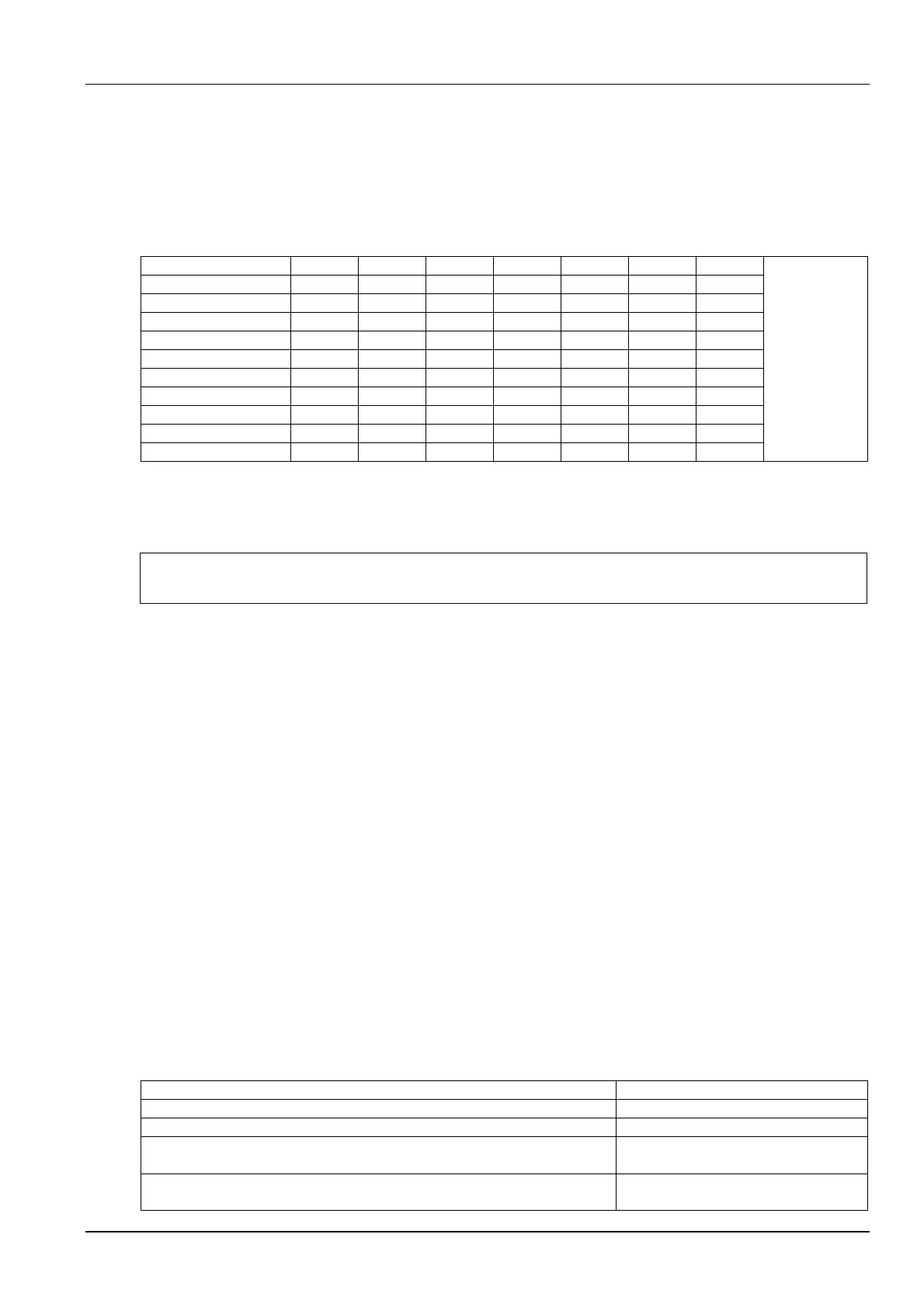
Rack temperature sensor IRM-S01T address setting is listed in Table 4-2.
Table 4-2 Rack temperature sensor IRM-S01T address setting
Sensor 1 2 3 4 5 6 ID
ON — “1”
OFF — “0”
Rack temperature 1 0 0 0 0 0 1 1
Rack temperature 2 0 0 0 0 1 0 2
Rack temperature 3 0 0 0 0 1 1 3
Rack temperature 4 0 0 0 1 0 0 10
Rack temperature 5 0 0 0 1 0 1 11
Rack temperature 6 0 0 0 1 1 0 12
Rack temperature 7 0 0 0 1 1 1 13
Rack temperature 8 0 0 1 0 0 0 20
Rack temperature 9 0 0 1 0 0 1 21
Rack temperature 10 0 0 1 0 1 0 22
Remote shutdown
As shown in Figure 4-3, terminals 37# and 38# can be connected to the remote shutdown switch. The terminals are
shorted before delivery. If a remote shutdown signal is to be connected, remove the short-connect cable.
Note
When terminals 37# and 38# are closed, the unit will shut down.
Control signals of outdoor unit
Terminals 70# & 71# are control signal input terminals of the outdoor unit. Their on and off state is the same as that of
the compressor 2#. They can be connected to the compressor rotation speed control terminals on the control board
of the outdoor unit, or you can choose not to connect them.
External common alarm
Terminals 75# and 76# can be connected to the external common alarms. They output signals to external alarm
devices, such as an alarm indicator. When critical alarm occurs, the contact will be closed to trigger remote alarms,
send signals to the building management system or dial the paging system automatically. The power supply of the
external common alarm system is user-prepared.
For the detailed definition of other terminals, refer to Appendix 1 Circuit Diagram.
4.2.4 Connecting Solenoid Valve Of Pipe Extension Kit (Option For Site Installation)
The solenoid valve of the pipe extension kit has two control cables, which are connected to the corresponding
terminals on the control board. For the specific connecting ports on the interface board, refer to the connecting
terminal number of liquid route solenoid valve in Appendix 1 Circuit Diagram.
4.3 Checklist For Completed Installation
After the electrical installation is completed, you should confirm the items listed in Table 4-3.
Table 4-3 Installation inspection
Check item Result
The power voltage is the same as the rated voltage on the unit nameplate
No open-circuit or short-circuit in the electrical connection exists
The power cables and earth cables connected to the disconnect switch, indoor unit
and outdoor unit are connected properly
The circuit breakers or fuses have proper ratings for equipment installed (refer to
the current listed in Table 4-1 for selecting apporopriate circuit breakers or fuses)
 Loading...