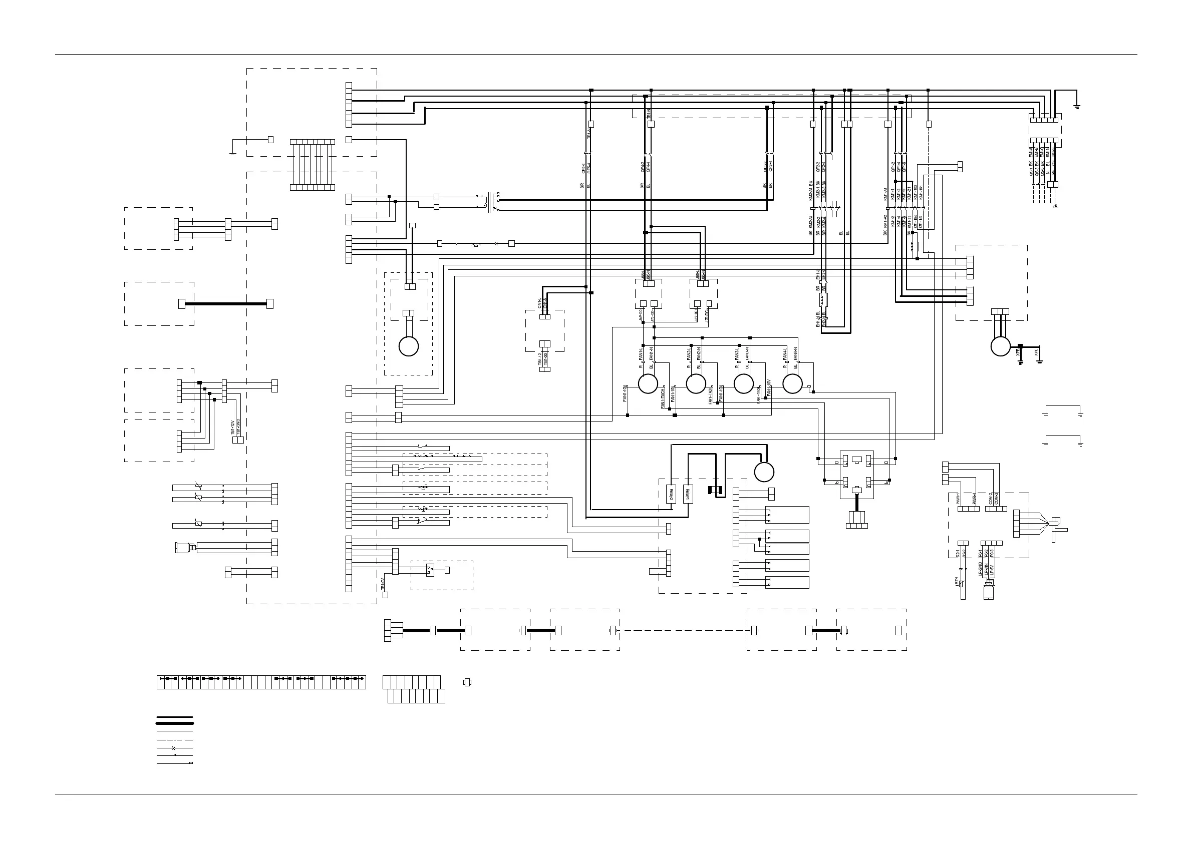
56 Appendix 1 Circuit Diagram
Liebert.CRV+ Series Air Cooled Precision Air Conditioner User Manual
380V~415V /60Hz 3N~
L2
3
4
L1
1
2
NL 3
6
5
2 4 6
1 5
Compressor
breaker
QF1
Main switch
QS
2 4
1 33
Humidifier
breaker
QF5
Factory supplied line voltage wiring
Factory supplied 24 volt wiring
Device own line
Notes:
Humidifier
pot
~
BK BK
Ethernet or CAN wiring
Inline quick disconnect
Wire color code:
BK- Black P- Purple
R-Red
WH-White
BL- Blue
BR-Brown
Y/GN-Yellow green
YE-Yellow
Terminal block connector
Naked crimping connector
J34J1
Temp .and Humi .
sensor
J21
1
2
3
4
5
6
BK
BR
BK
BR
BK
BR
7
8
BK
BR
J19
1
2
3
4
5
6
BK
BR
BK
BK
7
8
BK
BR
NC
Clogged filter alarm
COM
NO
1 2 3 4 5 6 7 8
J13
1
2
BK
BK
Transformer TC
TC-6
TC-5
BK
BK
4
TC-1
3
TC-2
J18
1
2
3
BK
BK
4
5
J31
1
2
BK
BK
1 2 3 4 5 6 7 8
J30
J29
8
7
6
5
4
3
BL
GR
BR
2
1
BK
1
2
J15-1
J15-2
BK
BR
0V
24V
24
51
TB2-51
TB2-24
1 2
High water alarm
1
2
BK
BR
1 2
24V
0V
J39
1
2
A1
B1
12V
GND
2
1
4
3
Humidifier board
TAM
BK BK
G
G0
ON
GND
DR
EV2
G
EV1
LS
LS
CS
CS
AL
AL
+ VR
SET
GND
AB
AB
2 4
1 3
Transformer
breaker
QF3
24V
0V
J28
1
2
3
4
5
6
7
8
9
10
Drain manually0
Humidify norminally1
Drain solenoid valve
Water level probe
Electrical conductivity
probe
J21-1
J21-2
J21-3
J21-4
J21-5
J21-6
J21-7
J21-8
J19-3
J19-4
J19-5
J19-6
J19-7
J19-8
J15
J18-T01
J31-1
J12-12V
J12- GND
J31-2
J13-1
J13-2
J18-T0- VAC
J12
J39-B
J39-A
BK
BR
ACM02U2
ACM 02A2
ACM02D1
J01
J01-7
J01-5
J01-3
J01-1
EEV controller
1
BK
J02-1
Humidifier alarm
Water under floor switch
38
37
Remote swith
TB2-37
TB2-38
1 2
A1
A2
2
1
4
3
6
5
22
21
Compressor
contactor
KM1
3 4
1 2
2 3
4
1
Fan 4Fan 3Fan2Fan
1
G10
10V
24VDC
power
module
Condensate
pump
J4
2
1
1
2
3
4
5
1 2 3 4
A1
B1
WS-2
Water line switch
WS-1
N
N
N
J28-1
J28-2
J02
1
J03
J03Y/G
PWR COM
EEV
S2 P0
BK
BR
Low pressure
sensor
BK
BR
J28-3
J28-4
76
75
Common alarm
TB 2-75
TB 2-76
Fan breaker
QF4
Optional
Optional
AL
AL
+ VR
SET
EV2
EV1
G
DR
GND
ON
LS
LS
CS
CS
G0
G
Optional
Optional
BR
J18-T02
Remote sensor 2
Remote sensor 1
Remote sensor 9 Remote sensor10
2 4 6
1 5
Heat
breaker
QF2
3
A1
A2
2
1
4
3
6
5
22
21
Heat
contactor
KM2
N N
ST1-C ST1-NC
Heat alarm
N
A1 B112V GND
J1-1 J1-2
ST2-C ST2-NC
Optional
94 95
EEV
153
SO4FI
High pressure alarm
70
71
Connection bars
N
A1
B1
12
00
Terminal block
GNDGND 12V12V B1 B124V24V0V A1A100 12 N N N NA1 B1G1010V 51 24 37 38 70 71 75 76
A2 B2 12VGND
94 95
TB1 TB2 TB3
GND12V
High pressure sensor
Exhaust air probe
RT3
Delivery air probe
1
RT1
A2
B2
12V
GND
RDU-SIC1
J23
1
2
3
J23-1
R
J23-2
BR
J23-3
BK
J8
1
2
J8-1
J8-2
BK
BK
J25
1
2
J25-1
J25-2
BK
BK
3
4
J14
1
2
J14-BBK
BR
12
GND
A
B
Delivery air probe
2
RT2
J25-3
J25-4
BK
BK
RDU-SIC2
12
GND
A
B
62
61
J20
1
2
J20-CANH
J20-CANL
BK
BR
BKJ18-T03
N
YE
WH
BK
BR
J19-1
J19-2
TB3
61 62 63 64
TB2
63
24V
TB1-24V
TB 2-63
Freon solenoid valve
Y1
XPE
XPE
BK
BK
J28-5
J28-6
64
Y1
Optional
0V
TB1-10V
TB1-G10
TB1-
TB1-
TB2-61
TB2-62
J14-A
TB2- B2
TB2- A2
J34J1
TB1-B1
TB1-A1
J4- GND
J4-12V
J4-A
J4-B
TB1- GND
TB1-12V
TB1-A1
TB1-B1
TB1-0V
TB1-24V
BK
BKTB1-0V
TB1-24V
TB1-94
TB1-95
BK
RE2 RE1
RE2 RE1
TB1-24V
TB1-0V
TB1-A1
TB1-B1
BK BR BR BK
TB 2-64
TB1-24V
TB 1-0V
AB
TB1-10V
TB1-G10
TB1-A1
TB1-B1
0V 0V 24V
12V GND
TB2- GND
TB2-12V
B
K
B
R
BK BK BK BK
BK
BK BRBK
TB2-70
TB2-71
GR-Grey
PEN
154
161
162
TB2
BK BR BK BR R
1
2 3
4
4FI -1
4FI -2
4FI -4
4FI -3
A` B` C` N`
A B C N
EMI
G`
G
1GND
2GND 3GND
4GND
L N
DC+ DC-
R48-1000 R48-1000
4
3
N
4FI -1GND
4FI-2 GND
4FI -4 GND
4FI -3 GND
J65
J69 J70
J65
J69 J70
L N
DC+ DC-
12VDC
power
module
12 00
EMI -A`
EMI -B`
EMI -C`
EMI -N`
EMI -G`
HP -5V
HP- VIN
HP-GND
Ground point of
the shield layer
Ground point of
the electrical
control box
L NCN1
V0+V0-CN 2
High Pressure Switch
FAN1-GND
YE
WH
FAN1- GND
YE
WH
FAN1- GND
YE
WH
FAN1-TACH
FAN 1-GND
HPS
HPS
Suction air probe
QF3-1
QF3-3QF5-1
QF4-1
QF4-3
HPS
12V
GND
A1
B1
12V
GND
TB1-
TB1-
12V
GND
BR BL
Grounding of
the cabinet
Grounding of
the cabinet
Grounding of
the back door
Grounding of
the front door
AC detection board
Display panel
50Hz
3~
Compressor
1
U V W
Compressor
transducer
12V
GND
A
B
L1
L2
L3
Ground point of
the cabinet
Y/G
Y/G
BK
BR
BR
BK
R
BK
BR+BK
BR
WH
WH
BK
BK
Filling solenoid valve
Control board
Power module Power module
Grounding of the
electrical control box
Figure 2 CR025 circuit diagram
 Loading...