Teamwork
77 Liebert
®
iCOM
®
for Liebert DSE
™
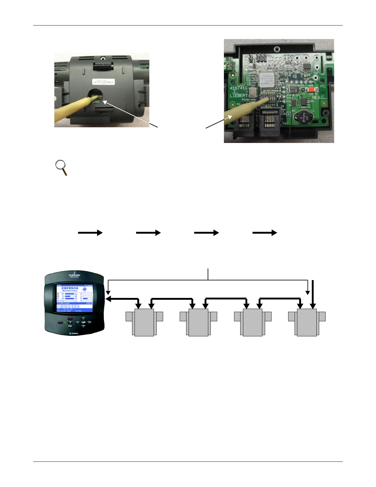
Figure 54 Setting 2T Sensor DIP Switches
4.3.3 Terminate the Final Sensor on the CANbus Link
2T Sensors do not need to be addressed in numerical order. For example, if four sensors are
purchased, they can be connected as shown in Figure 55.
Figure 55 2T sensor arrangement and termination
In the example above, if additional sensors are added to extend the existing sensor network, Sensor
#4 must be unterminated. The additional sensors can be connected. The last sensor in the extended
network must be terminated.
NOTE
Use included DIP switch tool (or similar tool). DO NOT insert any metal object
into the sensor case.
Non-conductive
DIP switch tool
2T sensor housing DIP switch hole
2T sensor housing case opened
Liebert iCOM Terminated Sensor #4Sensor #2 Sensor #3 Sensor #1
The key is to have the last sensor in the chain terminated.
CANbus
Communication Link
Terminated
Sensor
2T
#4
2T
#2
2T
#3
2T
#1