Configuration and Use Manual 173
Flowmeter Installation Types and Components
Diagrams Model 2500 CIOModel 1500 ANDefaults
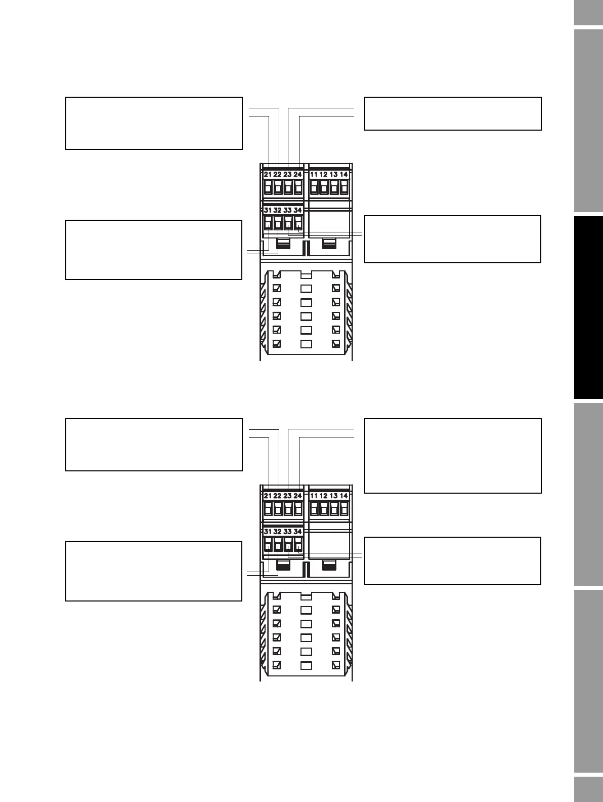
Figure B-6 Terminal configuration – Model 1500
Figure B-7 Terminal configuration – Model 2500
Terminals 21 & 22 (Channel A)
mA1 output
Internal power only
HART (Bell 202) communications
Terminals 23 & 24 (Channel B)
Not used
Terminals 31 & 32 (Channel C)
FO
Internal power only
No communications
mA = milliamp
FO = frequency output
Terminals 33 & 34
Service port OR Modbus RS-485
(Modbus RTU or Modbus ASCII)
Terminals 21 & 22 (Channel A)
mA1 output
Internal power only
HART (Bell 202) communications
Terminals 23 & 24 (Channel B)
mA2 output OR FO OR DO1
Power:
• mA – internal only
• FO or DO1 – internal or external
No communications
Terminals 31 & 32 (Channel C)
FO OR DO2 OR DI
Power: internal or external
No communications
mA = milliamp
FO = frequency output
DO = discrete output
DI = discrete input
Terminals 33 & 34
Service port OR Modbus RS-485
(Modbus RTU or Modbus ASCII)

 Loading...


