Configuration and Use Manual 195
Menu Flowcharts – Model 2500 CIO Transmitters
Diagrams Model 2500 CIOModel 1500 ANDefaults Diagrams Model 2500 CIOModel 1500 ANDefaults Diagrams Model 2500 CIOModel 1500 ANDefaults Diagrams Model 2500 CIOModel 1500 ANDefaults
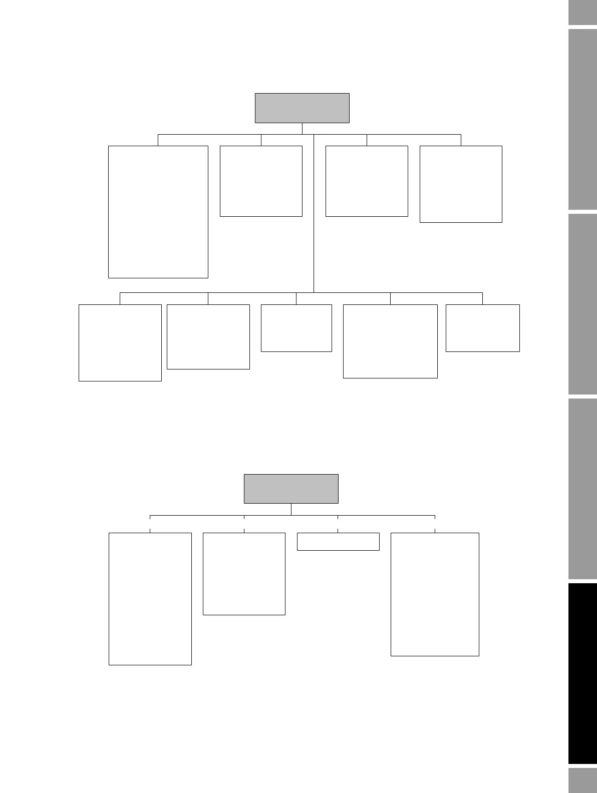
Figure D-4 ProLink II configuration menu continued
D.4 Communicator menus
Figure D-5 Communicator process variables menu
Sensor
•Sensor s/n
•Sensor model
•Sensor matl
• Liner matl
•Flange
ProLink >
Configuration
Transmitter options
• Volume flow
• Meter fingerprinting
• Meter verification
• API2540 Chapter 11.1
• Enhanced density
Alarm
•Alarm
•Severity
Variable mapping
•PV is
•SV is
•TV is
•QV is
Events
• Event 1/2
•Variable
•Type
•Setpoint
Discrete events
•Event name
•Event type
• Process variable
• Low setpoint (A)
• High setpoint (B)
Special units
• Base mass unit
• Base mass time
• Mass flow conv fact
• Mass flow text
• Mass total text
• Base vol unit
•Base vol time
• Vol flow conv fact
• Vol flow text
• Vol total text
System
• W & M approval
• Reset options
Polled variables
Polled variable 1/2
• Polling control
• External tag
• Variable type
•Current value
On-Line Menu >
2 Process variables
View fld dev vars
1 Mass flo
2 Temp
3 Mass totl
4 Dens
5 Mass inventory
6 Vol flo
7 Vol totl
8 Vol inventory
9 Pressure
View API vars
View ED vars
View output vars
1 View PV-Analog 1
2 View SV-Analog 2
3 View TV-Freq/DO
4 View QV
5 View event 1
6 View event 2
View status Totlizer contrl
1 Mass totl
2 Vol totl
3 Start totalizer
4 Stop totalizer
5 Reset all totals
6 Reset mass total
7 Reset volume total
8 Reset mass total
9 Reset ED volume
Reset gas std vol tot
2 3
4
1

 Loading...


