Configuration and Use Manual 193
Menu Flowcharts – Model 2500 CIO Transmitters
Diagrams Model 2500 CIOModel 1500 ANDefaults Diagrams Model 2500 CIOModel 1500 ANDefaults Diagrams Model 2500 CIOModel 1500 ANDefaults Diagrams Model 2500 CIOModel 1500 ANDefaults
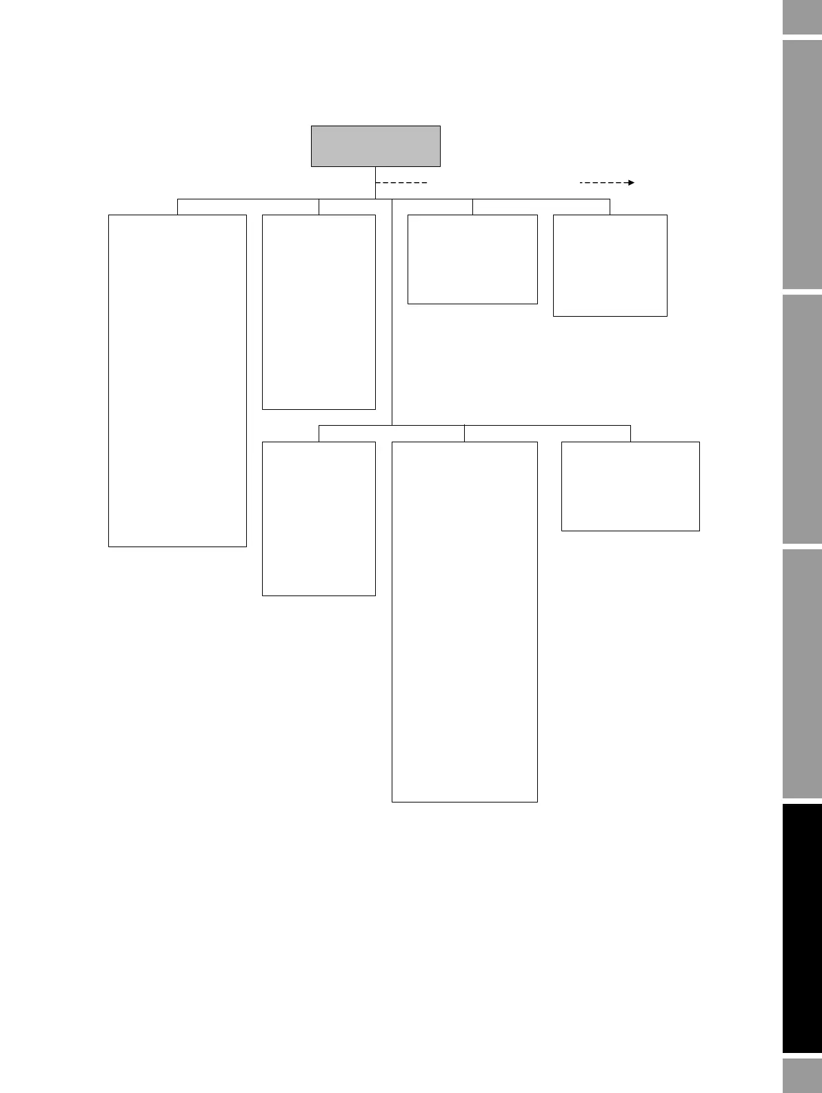
Figure D-2 ProLink II configuration menu
Flow
• Flow direction
•Flow damp
•Flow cal
• Mass flow cutoff
• Mass flow units
• Vol flow cutoff
• Vol flow units
• Vol flow type
• Std gas vol flow cutoff
• Std gas flow units
• Std gas density
Gas wizard
• Mass factor
• Dens factor
• Vol factor
• Enable entrained air
handling
• Flow switch variable
• Flow switch setpoint
Density
• Density units
• Density damping
• Slug high limit
• Slug low limit
• Slug duration
• Low density cutoff
•K1
•K2
•FD
•D1
•D2
• Temp coeff (DT)
Temperature
• Temp units
• Temp cal factor
• Temp damping
• External temperature
Pressure
•Flow factor
• Dens factor
• Cal pressure
• Pressure units
• External pressure
ProLink >
Configuration
Additional configuration options
Device
•Tag
•Date
• Descriptor
• Message
• Sensor type
• Transmitter serial number
• Floating pt ordering
• Add comm resp delay
Digital comm settings
• Fault setting
• HART address
• Loop current mode
•HART device ID
• Modbus address
• Enable write protection
Update rate
• Update rate
•100 Hz variable
Burst setup
• Enable burst
• Burst cmd
• Burst var 1...4
T Series
•FTG
•FFQ
•DTG
•DFQ1
•DFQ2
•K3
•D3
•D4
•K4
RS-485
•Protocol
•Parity
• Baud rate
• Stop bits

 Loading...


