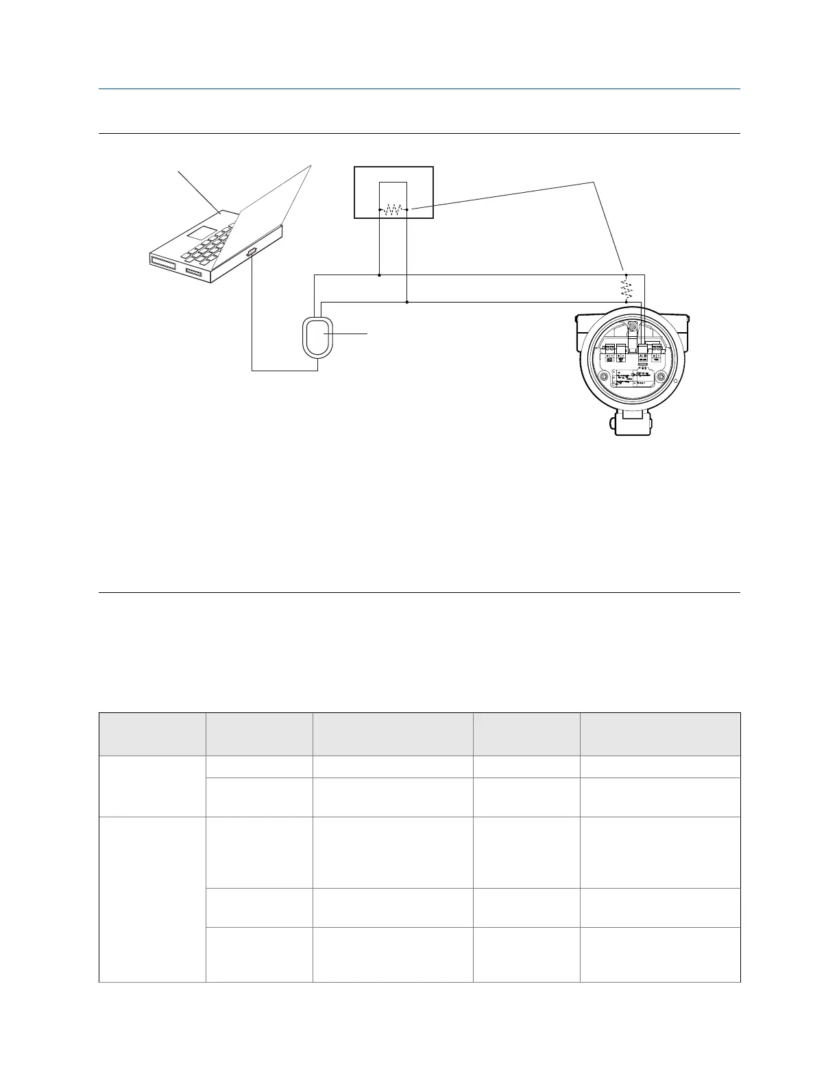
Connection over networkFigure C-2:
A. PC
B. RS‐232 to RS‐485 converter
C. 120-
Ω
, 1/2‐watt resistors at both ends of the segment, if necessary
D. DCS or PLC
E. Transmitter with end‐cap removed
Note
This figure shows a serial port connection. USB connections are also supported.
4. Start ProLink III.
5. Choose Connect to Physical Device.
6. Set the parameters that are required for your connection type.
RS-485 connection parametersTable C-1:
Connection type Parameter Value
Optional or re-
quired? Auto-detection
Service port Protocol Service Port Required No
PC Port The PC port that you are us-
ing for this connection.
Required No
Modbus/RS-485 Protocol Modbus RTU or Modbus ASCII Required Yes. The device accepts con-
nection requests that use ei-
ther protocol, and responds
using the same protocol.
PC Port The PC port that you are us-
ing for this connection.
Required No
Address The Modbus address config-
ured for this transmitter.
The default is 1.
Required No
Using ProLink III with the transmitter
Configuration and Use Manual 185

 Loading...


