EasyManuals Logo

Emerson Micro Motion Configuration And Use Manual

Emerson Micro Motion
212 pages
To Next Page IconTo Next Page
To Previous Page IconTo Previous Page
Page #203 background imageLoading...
Page #203 background image
Tip
HART connections are not polarity-sensitive. It does not matter which lead you attach to
which terminal.
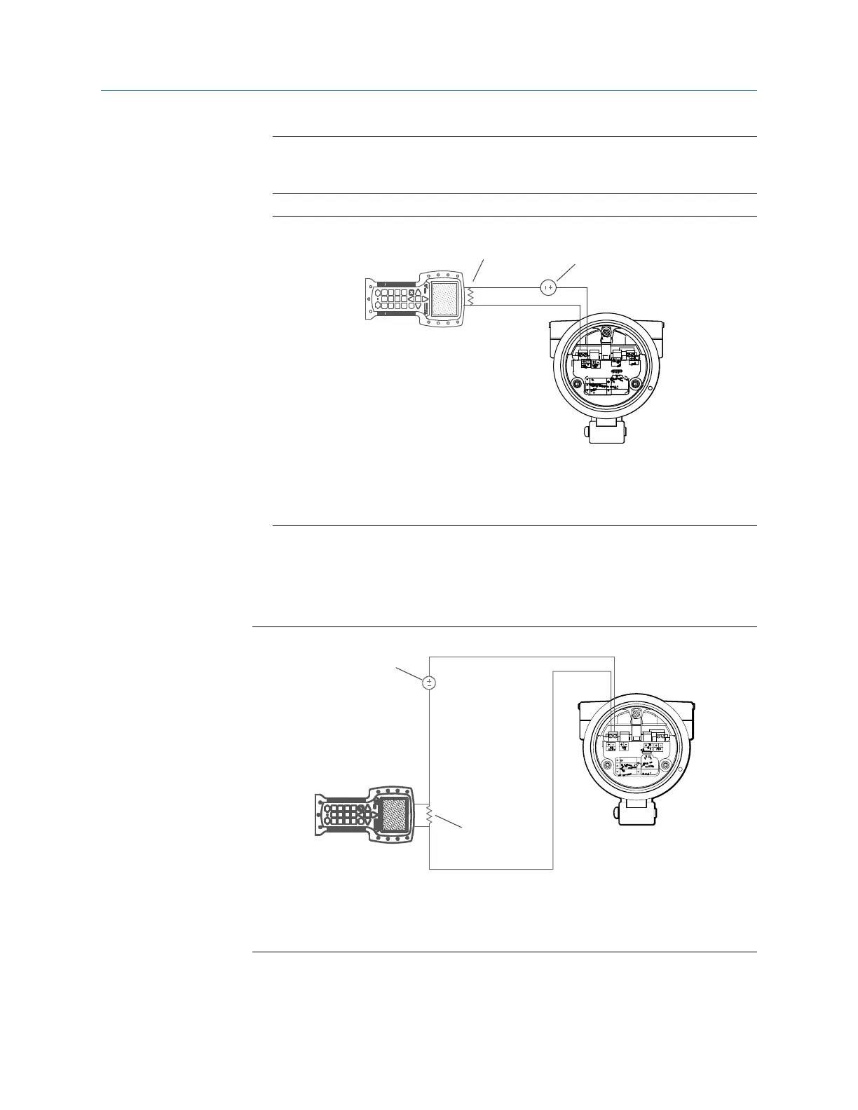
Field Communicator connection to transmitter terminalsFigure D-1:
A
B
C
D
A. Field Communicator
B. 250–600
resistance
C. External power supply
D. Transmitter with end‐cap removed
2. To connect to a point in the local HART loop, attach the leads from the
Field Communicator to any point in the loop and add resistance as necessary.
The Field Communicator must be connected across a resistance of 250–600 .
Field Communicator connection to local HART loopFigure D-2:
A
B
C
D
A. Field Communicator
B. 250–600
resistance
C. External power supply
D. Transmitter with end‐cap removed
3. To connect to a point in the HART multidrop network, attach the leads from the
Field Communicator to any point on the network.
Using the Field Communicator with the transmitter
Configuration and Use Manual 197

Table of Contents

Other manuals for Emerson Micro Motion

Questions and Answers:

Question and Answer IconNeed help?

Do you have a question about the Emerson Micro Motion and is the answer not in the manual?

Emerson Micro Motion Specifications

General IconGeneral
CategoryMeasuring Instruments
ManufacturerEmerson
BrandMicro Motion
TypeCoriolis Flow Meter
Output4-20 mA, HART, Foundation Fieldbus, Profibus, Modbus
Power Supply24 V DC
MaterialStainless Steel, Hastelloy
Process ConnectionFlanged, Threaded
CertificationsATEX, IECEx, CSA, SIL
Pressure RatingVaries by model; up to 10, 000 psi (690 bar)
Temperature RangeVaries by model; -400 to 750°F (-240 to 400°C)

Related product manuals