Safety
Information
Product
information
Mechanical
Installation
Electrical
installation
Getting
started
Basic
parameters
Running the
motor
Optimization
SMARTCARD
operation
Onboard
PLC
Advanced
parameters
Technical
data
Diagnostics
UL
information
Mentor MP User Guide 127
Issue: 3 www.controltechniques.com
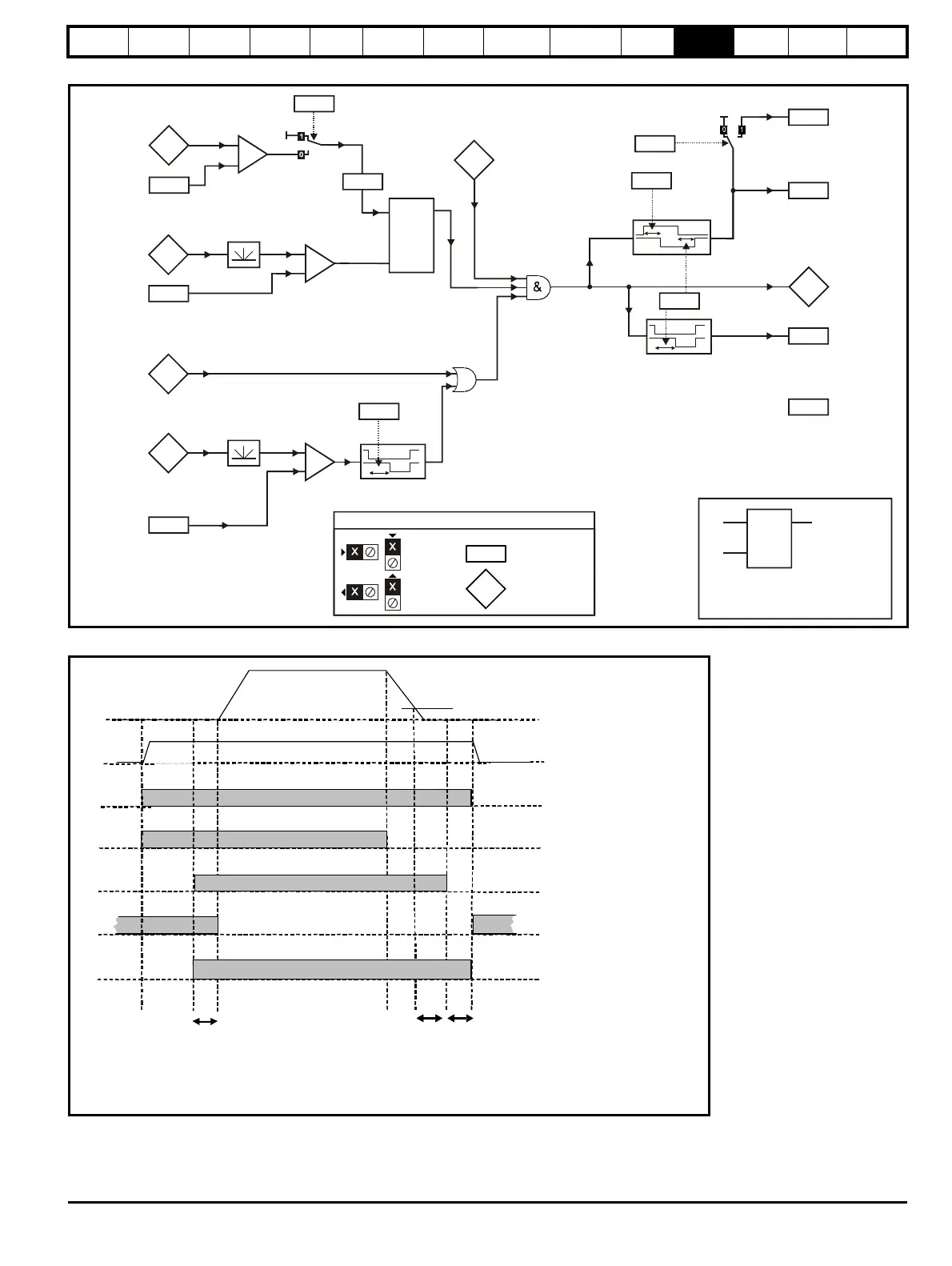
Figure 11-16 Menu 12 Brake control function
Figure 11-17 Brake sequence
Current
magnitude
3.02
Speed
feedback
Brake apply
speed
12.45
+
_
(RW)
parameter
Read-only (RO)
parameter
Input
terminals
Output
terminals
If the reset input is 1, the output is 0.
If the reset input is 0, the output latches
1.11
Reference
on
LAT
i
o
r
OR
Brake apply
speed delay
12.46
10.02
Drive active
Post-brake
release delay
Position
control
mode
( = 1)
5.54
Flux feedback
4.01
Lower current
threshold
12.43
+
_
5.70
+
_
enable
12.50
Field
active
External
field control
12.51
Torque present
80%
Rated field current
13.10
Pr Drive active
10.02
Torque present
1. Wait for armature current and fully fluxed machine
2. Post-brake release delay
3. Wait for speed threshold
4. Wait for brake apply speed delay
5. Brake apply delay
12.45
Pr
12.47
Pr Pr
12.46 12.48