Safety
Information
Product
information
Mechanical
Installation
Electrical
installation
Getting
started
Basic
parameters
Running the
motor
Optimization
SMARTCARD
operation
Onboard
PLC
Advanced
parameters
Technical
data
Diagnostics
UL
information
38 Mentor MP User Guide
www.controltechniques.com Issue: 3
• It can be used as a back-up power supply to keep the control circuits
of the drive powered up when the line power supply is removed. This
allows any fieldbus modules, application modules, encoders or serial
communications to continue to operate.
• It can be used to commission the drive when the line power supply is
not available, as the display operates correctly. However, the drive
will be in the UV trip state unless the line power supply is enabled,
therefore diagnostics may not be possible. (Power down save
parameters are not saved when using the 24V back-up power
supply input.)
The working voltage range of the 24V power supply is as follows:
Maximum continuous operating voltage: 30.0V
Minimum continuous operating voltage: 19.2V
Nominal operating voltage: 24.0V
Minimum start up voltage: 21.6V
Maximum power supply requirement at 24V: 60W
Recommended fuse: 3 A, 50Vdc
Minimum and maximum voltage values include ripple and noise. Ripple
and noise values must not exceed 5%.
4.6 Cable and fuse size ratings
Maximum continuous input currents are given in section 2.1 Ratings on
page 6 to aid the selection of fuses and cabling. The maximum input
current is dependent on the ripple content of the output current. A value
of 100% ripple has been assumed for the given ratings.
The cable sizing selected when installing a Mentor MP must comply with
the local wiring regulations. The information provided in this section is
provided for guidance purposes only.
The power terminals on Mentor MP frame size 1 drives have been
designed to accommodate a maximum cable size of 150mm
2
(350kcmil)
with a temperature of 90°C (194°F).
The power terminals on Mentor MP frame size 2A drives have been
designed to accommodate a maximum cable size of 2 x 150mm
2
(2 x
350kcmil) with a temperature of 75°C (167°F).
The power terminals on Mentor MP frame size 2B drives have been
designed to accommodate 2 x 240mm
2
with a temperature of 90°C
(194°F). The use of cables sized using the US national electrical code as
shown in Table 4-8 requires the use of a terminal adaptor.
The power terminals on Mentor MP frame size 2C and 2D drives have
been designed for use with busbars. The drive can be used with cables
as shown in Table 4-8 with the use of a terminal adaptor.
The actual cable size depends on a number of factors including:
• Actual maximum continuous current
• Ambient temperature
• Cable support, method and grouping
• Cable voltage drop
In applications where the motor used is of a reduced rating, the cable
sizing selected can be appropriate for that motor. To protect the motor
and the output cabling the drive must be programmed with the correct
motor rated current.
When using reduced cable sizes, the branch circuit protection fuse rating
needs to be reduced in line with the cable size selected.
The following table shows typical cable sizes based on USA and
International standards, assuming 3 conductors per raceway/conduit, an
ambient temperature of 40°C (104°F) and applications with high output
current ripple content.
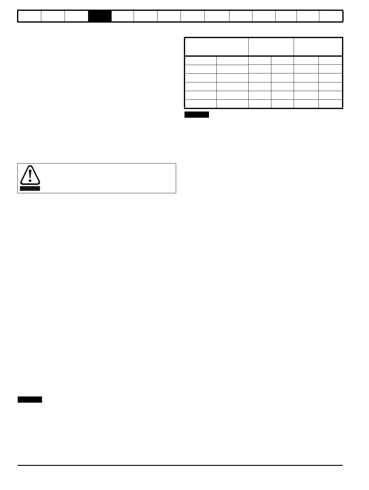
Table 4-6 Typical cable sizes for size 1 drives
1. The maximum cable size is defined by the power terminal housing
using 90°C (194°F) rated cables as per Table A.52-5 of the standard.
2. Assumes the use of 75°C rated cables, as per Table 310.16 of the
National Electrical Code.
The use of higher temperature rated cable would allow a reduction on
the minimum recommended cable size for Mentor MP shown above. For
high temperature cable sizing, please refer to the data supplied by the
manufacturer of the high temperature cable.
The selection of the correct fuse is essential to ensure the
safety of the installation
Model
IEC 60364-5-52
[1]
UL508C/NEC
[2]
Input Output Input Output
MP25A4(R) MP25A5(R)
2.5mm
2
4mm
2
8 AWG 8 AWG
MP45A4(R) MP45A5(R)
10mm
2
10mm
2
4 AWG 4 AWG
MP75A4(R) MP75A5(R)
16mm
2
25mm
2
1 AWG 1/0 AWG
MP105A4(R) MP105A5(R)
25mm
2
35mm
2
1/0 AWG 1/0 AWG
MP155A4(R) MP155A5(R)
50mm
2
70mm
2
3/0 AWG 4/0 AWG
MP210A4(R) MP210A5(R)
95mm
2
95mm
2
300kcmil 350kcmil