Safety
Information
Product
information
Mechanical
Installation
Electrical
installation
Getting
started
Basic
parameters
Running the
motor
Optimization
SMARTCARD
operation
Onboard
PLC
Advanced
parameters
Technical
data
Diagnostics
UL
information
Mentor MP User Guide 49
Issue: 3 www.controltechniques.com
If the CT Comms cable is to be used, then pin 6 (TX enable) should be
connected on all drives and pin 4 (+24V) should be linked to at least 1
drive to supply power to the converter in the cable.
Only one CT Comms cable can be used on a network.
4.11 Shield connections
These instructions must be followed to ensure suppression of radio-
frequency emission and good noise immunity in the encoder circuit. It is
recommended that the instructions for the connection of the encoder
cable be followed closely and, to use the grounding bracket and
grounding clamp supplied with the drive, to terminate the shields at the
drive.
4.11.1 Motor cables
Use of a motor cable with an overall shield for the armature and field
circuits may be needed if there is a critical EMC emissions requirement.
Connect the shield of the motor cable to the ground terminal of the motor
frame using a jumper (link) that is as short as possible and not
exceeding 50mm (2in) long. A full 360° termination of the shield to the
terminal housing of the motor is beneficial.
4.11.2 Encoder cable
To get the best results from shielding use cable with an overall shield
and separate shields on individual twisted pairs. Refer to section
4.15 Connecting an encoder on page 54.
4.11.3 Control cables
It is recommended that signal cables should be shielded. This is
essential for encoder cables, and strongly recommended for analog
signal cables. For digital signals it is not necessary to use shielded
cables within a panel, but this is recommended for external circuits,
especially for inputs where a momentary signal causes a change of state
(i.e. latching inputs).
4.11.4 Grounding hardware
The drive is supplied with a grounding bracket, to facilitate EMC
compliance. This provides a convenient method for direct grounding of
cable shields without the use of "pig-tails". Cable shields can be bared
and clamped to the grounding bracket using metal clips, clamps or cable
ties. Note that the shield must in all cases be continued through the
clamp to the intended drive terminal in accordance with the connection
details for the specific signal.
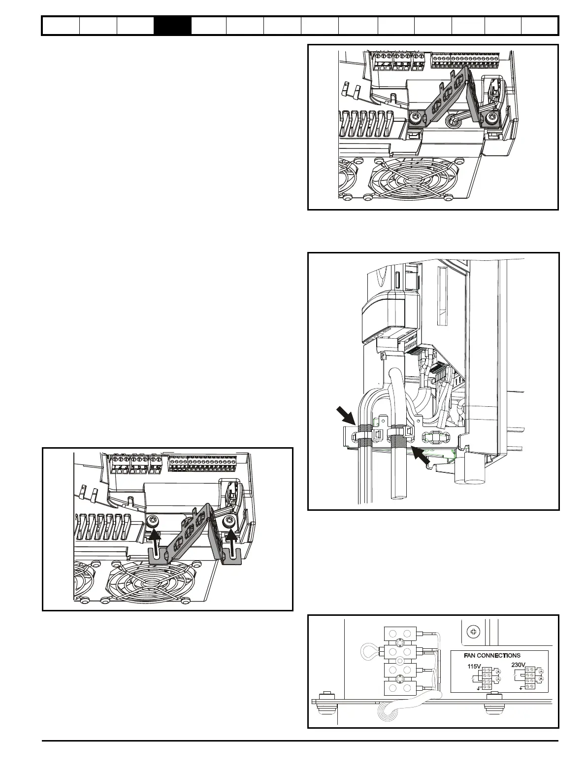
Figure 4-17 Fitting of grounding bracket
Loosen the ground connection (2 x M5 x 10) screws using T25 Torx
driver and slide the grounding bracket in the direction shown. Once in
place, re-tighten the ground connection M5 x 10 screws to 3Nm (2.21 Ib
ft).
A faston tab is located on the grounding bracket for the purpose of
connecting the drive 0V to ground should the user wish to do so.
Figure 4-18 Grounding of signal cable shields using the
grounding bracket
4.12 Connecting the fan on size 2C and 2D
drives
A supply needs to be connected to the dual fan unit enclosed within the
lower duct on Mentor MP size 2C and 2D. The fans can be configured
for a 230Vac (factory setting) or 115Vac supply as shown below on the
label next to the fan connections. When connecting the fan supply, the
screws should be tightened with a maximum torque of 1.2 Nm (0.88 Ib ft)
to 2 Nm (1.47 Ib ft).
Figure 4-19 Fan connection