Safety
Information
Product
information
Mechanical
Installation
Electrical
installation
Getting
started
Basic
parameters
Running the
motor
Optimization
SMARTCARD
operation
Onboard
PLC
Advanced
parameters
Technical
data
Diagnostics
UL
information
Mentor MP User Guide 57
Issue: 3 www.controltechniques.com
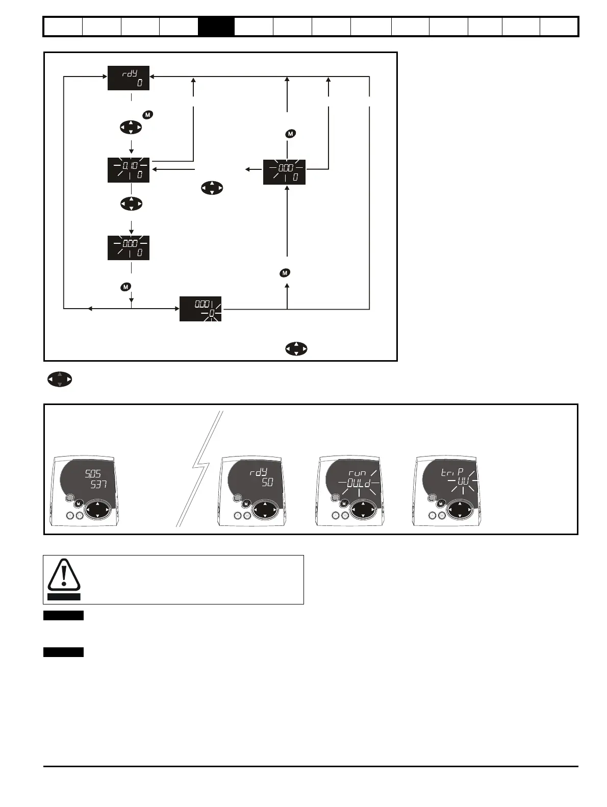
Figure 5-3 Display modes
Figure 5-4 Mode examples
When changing the values of parameters, make a note of the new
values in case they need to be entered again.
For new parameter-values to apply after the AC supply to the drive is
interrupted, new values must be saved (section 5.8 Saving
parameters on page 61).
Use
* keys
to select parameter for editing
To enter Edit Mode,
press key
Status
Mode
(Display
not
flashing)
Parameter
Mode
(Upper
display
flashing)
Edit Mode
(Character to be edited in lower line of display flashing)
Change parameter values
using keys.
When returning
to Parameter
Mode use the
keys to select
another parameter
to change, if
required
To exit Edit Mode,
press key
To enter Parameter
Mode, press key or
*
Temporary
Parameter
Mode
(Upper display
flashing)
Timeout**
Timeout**
To return to
Status Mode,
press
key
RO
parameter
R/W
parameter
* Can only be used to move between menus if L2 access has been enabled Pr 11.44 (SE14, 0.35)
**Time-out defined by Pr 11.41 (default value = 240s).
Pr value
5.05
Menu 5. Parameter 5
Trip type (UV = undervolts)
Drive status = tripped
Trip StatusAlarm Status
Parameter
View Mode
Healthy Status
Status Mode
Do not change parameter values without careful
consideration; incorrect values may cause damage or a
safety hazard.